寄什么快递最便宜| 蛀牙是什么原因引起的| 维c之王是什么水果| 吃饭后胃胀是什么原因| 属虎的本命佛是什么佛| 1月16日什么星座| 黄瓜有什么营养价值| 过敏了吃什么药好| 1月7日是什么星座| 乌灵参是什么东西| 五心烦热是什么意思| 下面痛是什么原因| 黄体生成素高是什么原因| 拉屎发黑是什么原因| 吃什么健脾| 甲胎蛋白偏高说明什么| 女人做梦哭醒预示什么| 甲低有什么症状表现| 老人爱睡觉是什么原因| 什么车可以闯红灯| 大哥是什么意思| 早上口干苦是什么原因| 寄生虫吃什么药可以杀死| 潭柘寺求什么最灵验| 什么食物降血压| 水痘可以吃什么水果| 苛捐杂税是什么生肖| 不劳而获是什么生肖| 治肝病最好的药是什么药| 正切是什么| 1999年属兔是什么命| 边缘性脐带入口是什么意思| 梦见捉蛇是什么意思| 心脏早博是什么意思| 重阳节的习俗是什么| 总放屁还特别臭是什么原因| 孕激素高会有什么影响| 来曲唑片是什么药| 文采是什么意思| 梦到自己孩子死了是什么征兆| 男人梦见鱼是什么征兆| 榴莲不可以和什么一起吃| 惜字如金是什么意思| 玖字五行属什么| 家庭教育是什么| 早上6点半是什么时辰| 总胆固醇高是什么意思| 阳历3月是什么星座| 无菌性前列腺炎吃什么药效果好| 间歇性跛行是什么意思| 超敏c蛋白反应高是什么原因| 枕大池增大什么意思| 什么水果治便秘| 卵泡排出来是什么样的| 肝火旺吃什么中成药| 茉莉花茶是什么茶| 子宫肌瘤都有什么症状| 子宫前位和子宫后位有什么区别| 男孩叫什么名字| 11.23是什么星座| 谢霆锋什么学历| 疱疹感染是什么病| 脑供血不足什么症状| cnc是什么牌子| 下体痒是什么原因| 26周岁属什么| 拉肚子吃什么水果| 颈椎钙化是什么意思严重么| 笑靥什么意思| 什么草药可以止痒| 什么也别说| 空调出风小没劲什么原因| 化疗后吃什么排毒最快| 皮的偏旁是什么| 6月18日是什么星座| 沙姜是什么姜| 胆汁反流什么症状| 功能是什么意思| 水能变成什么| 房性期前收缩是什么意思| 三月十五日是什么星座| 水疱疹什么药最快能治好| 保家仙是什么| 抽血化验挂什么科| 小孩晚上睡觉磨牙是什么原因| 大乌龙是什么意思| 什么是裸分| 腰酸是什么原因引起的| 摸摸唱是什么| 小三阳吃什么食物好得快| 宫颈口大是什么原因| 公安局局长是什么级别| 升阳是什么意思| 四海是什么意思| 人在什么情况下会发烧| 轶事是什么意思| 幽门螺杆菌是什么病| hpv52阳性有什么症状| 点痣用什么方法最好| 益母草什么时候喝最好| 哈森鞋子属于什么档次| 男人肾虚吃什么最补| 大便少是什么原因| 子宫前位是什么意思| 过敏擦什么药膏好得快| 低密度灶是什么意思| 马虎眼什么意思| 为什么要做羊水穿刺检查| 子宫附件彩超检查什么| 拉架棉是什么面料| 总胆汁酸高吃什么药| 学生是什么阶级| 核酸是什么| 痛经挂什么科| 什么病误诊为帕金森| 野兽之王是什么动物| 生蚝有什么功效与作用| 老花眼有什么办法可以恢复| 肠道易激惹综合征的症状是什么| 清官是什么意思| oc是什么| 窦骁的父母是干什么的| 什么水果含维生素d| 左耳疼痛什么原因引起| ct和核磁共振有什么区别| 湿疹有什么症状| 婴儿放屁多是什么原因| 猫传腹是什么病| 脚心出汗是什么原因女| 冬天手脚冰凉是什么原因怎么调理| 牙冠什么材质的好| 海参不适合什么人吃| 80岁属什么生肖| 臭屁是什么意思| 红油抄手是什么| 丙磺舒是什么药| 什么什么一什么| 貂蝉属什么生肖| 阳历九月份是什么星座| 吃什么食物补气血| 手五行属什么| gmp认证是什么意思| 女人手心热吃什么调理| 吃什么升血小板最快最好| 副旅长是什么军衔| xxs是什么意思| 晕车药什么时候吃| 屁多还臭是什么原因| 身体皮肤痒是什么原因| 红指什么生肖| 欧根纱是什么面料| 肉桂属于什么茶| 鸭子喜欢吃什么| 阑尾炎不能吃什么| bp是什么意思| 三妻四妾是什么意思| 副教授是什么级别| 人参果是什么季节的| 大便不成形吃什么中成药| 心肌桥是什么病| 冬瓜什么时候种植最好| 什么方法避孕最安全有效| 不典型血管瘤什么意思| 农历12月18日是什么星座| 大腿根部疼痛是什么原因| 女生肚子疼是什么原因| 中学为体西学为用是什么意思| 欢愉是什么意思| 滇红是什么茶| 骨质疏松是什么原因引起的| 遇上方知有什么意思| 吃什么对甲状腺有好处| 肚子疼喝什么能缓解| 上火便秘吃什么最快排便| 心痛吃什么药效果好| 不动产权是什么意思| 挂职是什么意思| 看到黄鼠狼什么预兆| 风热感冒吃什么| 七活八不活是什么意思| 二氧化硅是什么晶体| 月经推迟是什么原因| 手背出汗是什么原因| 颈肩综合症有什么症状| coco什么意思| 头顶冒汗是什么原因| 什么是宦官| 医生规培是什么意思| 死心眼什么意思| 血管堵塞有什么症状| 绿树成荫是什么季节| m2是什么单位| 印度信仰什么教| 9月份有什么节日| 啤酒酵母是什么| 7月17日是什么日子| 组织机构代码是什么| 睡眠模式是什么意思| 取笑是什么意思| 乳腺炎吃什么药好| ed50是什么意思| 封闭针是什么| 砼为什么念hun| 脑萎缩是什么原因| 小便不舒服吃什么药| 姜维属什么生肖| 为什么近视不可逆| 住房公积金缴存基数是什么意思| 女方起诉离婚需要什么证件| 攻击的近义词是什么| 白皮鸡蛋是什么鸡下的| 干咳嗽无痰是什么原因| 1月3日什么星座| 爱吃酸的人是什么体质| 脾胃不好吃什么水果| 湿疹为什么晚上特别痒| 6月26日什么星座| 心火旺失眠吃什么药| 晚上吃什么饭| 悟空是什么意思| 晚上3点是什么时辰| 嫖娼是什么意思| 乐五行属什么| 圻字五行属什么| 梅毒通过什么传播| 将军指什么生肖| 三七粉是什么| 什么空调| 水代表什么生肖| 橙子不能和什么一起吃| 减肥期间早餐应该吃什么| 先天性聋哑病属于什么遗传病| 1983年出生是什么命| 没有润滑油用什么代替| 什么颜色属木| 泾渭分明是什么意思| 塬字五行属什么| 晚餐吃什么减肥| 什么是事业编| 老保是什么意思| 硌得慌是什么意思| 蜂蜜可以做什么美食| 面瘫什么意思| 红痣是什么原因引起的| 加持什么意思| 外阴白斑用什么药最好| 苍蝇为什么喜欢往人身上飞| 购物狂是什么心理疾病| 右眼皮跳是什么预兆男| 中国的四大发明是什么| 7月30号是什么星座| 宝妈男是什么意思| 炙子是什么意思| 世界上最大的海是什么海| 智齿什么时候开始长| 梦见自己吃肉是什么预兆| 拔凉拔凉是什么意思| 排尿困难吃什么药| 牙龈是什么| 什么是水马| 韭菜炒什么好吃| 蛋白尿是什么原因引起的| 罗网是什么意思| oct试验是什么| 百度

时尚与都市 GUCCI腕表发布一系列G-FRAME表款

Diagram layout patterns Download PDF

Info

Publication number
US8453107B2
US8453107B2 US12/271,699 US27169908A US8453107B2 US 8453107 B2 US8453107 B2 US 8453107B2 US 27169908 A US27169908 A US 27169908A US 8453107 B2 US8453107 B2 US 8453107B2
Authority
US
United States
Prior art keywords
diagram
pattern
pattern definition
attributes
property
Prior art date
Legal status (The legal status is an assumption and is not a legal conclusion. Google has not performed a legal analysis and makes no representation as to the accuracy of the status listed.)
Expired - Fee Related, expires
Application number
US12/271,699
Other versions
US20100125825A1 (en
Inventor
Stephen M. Danton
Jordan C. Sehn
Michael C. Murray
Florian W. H. Voss
Scott M. Roberts
Current Assignee (The listed assignees may be inaccurate. Google has not performed a legal analysis and makes no representation or warranty as to the accuracy of the list.)
Microsoft Technology Licensing LLC
Original Assignee
Microsoft Corp
Priority date (The priority date is an assumption and is not a legal conclusion. Google has not performed a legal analysis and makes no representation as to the accuracy of the date listed.)
Filing date
Publication date
Application filed by Microsoft Corp filed Critical Microsoft Corp
Priority to US12/271,699 priority Critical patent/US8453107B2/en
Assigned to MICROSOFT CORPORATION reassignment MICROSOFT CORPORATION ASSIGNMENT OF ASSIGNORS INTEREST (SEE DOCUMENT FOR DETAILS). Assignors: SEHN, JORDAN C., DANTON, STEPHEN M., MURRAY, MICHAEL C., ROBERTS, SCOTT M., VOSS, FLORIAN W. H.
Publication of US20100125825A1 publication Critical patent/US20100125825A1/en
Priority to US13/875,919 priority patent/US8856730B2/en
Application granted granted Critical
Publication of US8453107B2 publication Critical patent/US8453107B2/en
Assigned to MICROSOFT TECHNOLOGY LICENSING, LLC reassignment MICROSOFT TECHNOLOGY LICENSING, LLC ASSIGNMENT OF ASSIGNORS INTEREST (SEE DOCUMENT FOR DETAILS). Assignors: MICROSOFT CORPORATION
Expired - Fee Related legal-status Critical Current
Adjusted expiration legal-status Critical

Links

Images

Classifications

    • GPHYSICS
    • G06COMPUTING; CALCULATING OR COUNTING
    • G06FELECTRIC DIGITAL DATA PROCESSING
    • G06F40/00Handling natural language data
    • G06F40/10Text processing
    • G06F40/103Formatting, i.e. changing of presentation of documents
    • GPHYSICS
    • G06COMPUTING; CALCULATING OR COUNTING
    • G06TIMAGE DATA PROCESSING OR GENERATION, IN GENERAL
    • G06T11/002D [Two Dimensional] image generation
    • G06T11/60Editing figures and text; Combining figures or text

Definitions

  • Computers and computing systems have affected nearly every aspect of modern living. Computers are generally involved in work, recreation, healthcare, transportation, entertainment, household management, etc.
  • a diagram generally, is a collection of one or more shapes and/or connecting lines.
  • the diagrams can represent, for example, a workflow model, a business process model, or other flow or process. Shapes and connections or lines can be used for other purposes as well.
  • lines are not necessarily single straight lines, but may also include rectilinear, curvilinear or other representations.
  • Diagramming layout systems typically allow for free form definitions of diagrams, such as by user interaction with graphical representations of shapes and lines.
  • existing systems provide rudimentary control over how the diagram responds given specific sets of data, e.g. a workflow diagram versus a business process model, they lack the ability to define rules on a “per node” or “per connection” basis.
  • One embodiment described herein includes a method of defining a layout of diagram elements.
  • the method includes receiving user input.
  • the user input includes one or more declarative statements specifying conditional patterns based on attributes of diagram elements.
  • the conditional patterns define layouts of diagram elements. Implementation of the layouts is dependent on conditions defined in the declarative statements and one or more values of one or more of the attributes.
  • the method further includes organizing the conditional patterns as a pattern definition.
  • the pattern definition is stored on a computer readable medium.
  • the pattern definition is stored such that the pattern definition is retrievable by an application program that uses the pattern definition to evaluate the conditional patterns using values of attributes of one or more diagram elements.
  • the application is also configured to display representations of the diagram elements according to the layouts when conditions for implementing the layouts are satisfied.
  • Another embodiment includes a method which may be practiced in a computing environment.
  • the method includes acts for facilitating defining a diagram layout.
  • the method includes displaying a representation of a diagram, where the diagram includes one or more elements including one or more shapes or lines.
  • the method further includes receiving user input.
  • the user input includes one or more declarative statements specifying conditional patterns based on attributes of diagram elements.
  • the conditional patterns are evaluated using attributes of the one or more shapes or lines.
  • the representation of the diagram is updated based on evaluating the conditional patterns using attributes of the one or more shapes or lines.
  • the updated representation of the diagram is displayed.
  • Yet another embodiment includes a method that may be practiced in a computing environment.
  • the method includes acts for displaying diagrams.
  • the method includes receiving one or more rules.
  • the rules include one or more declarative statements specifying one or more conditional diagram layout patterns based on one or more attributes of diagram elements.
  • the one or more rules are evaluated using one or more attributes of one or more elements of a diagram. Based on evaluating the one or more rules using one or more attributes of one or more elements of the diagram, a representation of the diagram is created and the representation of the diagram is displayed.
  • FIG. 1 illustrates an example of a diagram layout
  • FIG. 2 illustrates relative Y positioning of a diagram layout
  • FIG. 3 illustrates relative X positioning of a diagram layout
  • FIG. 4 illustrates an example diagram layout
  • FIG. 5 illustrates an example diagram layout
  • FIG. 6 illustrates a method including acts for creating and storing pattern definitions
  • FIG. 7 illustrates a method including acts for updating diagram representations
  • FIG. 8 illustrates a method including acts for evaluating rules and displaying representations.
  • layout patterns include user defined layout rules that apply only when the conditions of the pattern are met.
  • the conditions may be defined in metadata about shapes, lines, and/or diagrams (which include collections of one or more shapes and one or more lines).
  • a pattern may include rules that specify that decision diamond boxes should always have lines flowing from the right hand side and the bottom.
  • Other rules may specify sizes, orientations, centers, relative positioning, etc. based on information about diagrams or diagram elements.
  • the information may be related to any of a number of different factors or conditions.
  • the information may be related to object shapes themselves as illustrated in the diamond decision box example above.
  • the information may be related to how the diagram will be used, such as for what industry sector or business environment.
  • the information may be related to hardware characteristics where a diagram is rendered, such as screen size, processor power, available memory, etc. Other factors may be used in various alternative embodiments.
  • rules in a definition may specify use of a merged connection routing pattern when a node matches a “decision” pattern.
  • a layout pattern may be defined by a pattern definition and a set of associated setters as will be discussed in more detail below.
  • the pattern definition includes an enumeration of characteristics of diagrams, while the setters specify attributes that are applied to diagrams meeting the characteristic definitions.
  • Layout patterns may be scoped to a particular layout type.
  • a layout pattern may be scoped to a hierarchy or model type.
  • default patterns can be defined for layout type and thereby be used in the absence of additional configuration. In some embodiments, this may be expressed through a hierarchy layout.
  • layout patterns may specify one or more of: number of connections, incoming vs. outcoming for a shape, direction of connection, general entity type, etc
  • embodiments may be implemented where patterns can be saved for reuse and combination with other patterns.
  • patterns may be organized hierarchically when used with other patterns. Some embodiments may allow for multiple patterns for a given situation and have patterns optionally triggered. Further, embodiments may include functionality configured to detect conflicts between patterns and to provide such information to a user.
  • the following discussion includes a number of examples illustrating different metadata properties and setters that may be specified in a layout pattern.
  • FIG. 1 illustrates a source block or node 102 , a decision block or node 104 , and three activity blocks or nodes 106 , 108 and 110 .
  • An OutgoingEdges property for the source node 102 may specify a property value of 1.
  • An OutgoingEdges property for the decision node 104 may specify a property value of 3.
  • An OutgoingEdges property for each of the activity nodes may specify property values of 0.
  • IncomingEdges property defines the number of edges entering a shape.
  • values of this property may be: 0, 1, or n, where n is a positive integer number.
  • This property may have a default value assigned, such as 0, 1 or some other default value.
  • each of the nodes, except the source node 102 may have an IncomingEdges property value of 1.
  • the source node 102 may have an IncomingEdges property value of 0.
  • Depth property defines the depth in the tree relative to a root node. In some embodiments, this property applies to directed diagrams only. For example, this property may apply to directed graphs. In the present example, values of this property may be any integer. The default value of this property may be any integer.
  • Orientation property Another property that is used in the examples illustrated herein is the Orientation property. This property defines the current orientation of the shape or diagram.
  • IsRotated property This property defines rotation state relative to parent node.
  • values of this property may be: TRUE or FALSE. If the property value is TRUE, then a node to which the property applies is rotated in “horse” fashion relative to a parent node. The default value of this property is False in this example.
  • IsSource property specifies if the node is a source. In the present example, values of this property may be: TRUE or FALSE. If the property value is TRUE, then node is a source. The default value of this property is NULL in this example. For example, in FIG. 1 , the source node 102 may have an IsSource property value of TRUE, while the other nodes 104 - 110 have IsSource vales of FALSE.
  • RelativeTop property specifies position of node relative to an associated node with respect to top-bottom arrangement, based on the center point of the two nodes.
  • values of this property may be: 1, 0, ? 1. If the value of this property is 1, the node to which it applies has a higher Y coordinate than the associated node. An example of this is illustrated by diagram 202 in FIG. 2 . If the value of this property is ? 1, the node to which it applies has a lower Y coordinate than the associated node. An example of this is illustrated at diagram 204 in FIG. 2 . If the value of this property is 0, then the node to which it applies has the same Y coordinate as the associated node. An example of this is illustrated by diagram 206 in FIG. 2 . The default value of this property is NULL in this example.
  • FIG. 2 illustrates examples of behaviors for different values for the RelativeTop property.
  • RelativeLeft property Another property that is used in the examples illustrated herein is the RelativeLeft property. This property is similar to the RelativeTop property, but with respect to left-right arrangement. In the present example, values of this property may be: 1, 0, ? 1. If this property has a value of 1, then the relevant node's X is greater than an associated node. An example of this is illustrated at 302 . If this property has a value of ? 1, then the relevant node's X is less than associated node. An example of this is illustrated at 304 in FIG. 3 . If this property has a value of 0, then the relevant node's X is equal to an associated node. An example of this is illustrated at 304 in FIG. 3 . The default value for this property in the present examples is NULL.
  • Example pattern triggers are illustrated below. These are only representative and by no means exhaustive.
  • Any pattern that is constructed by the user can be saved and then reused in other diagrams or at different locations in the same diagram. As such it is safe to view patterns as isolated units that can be reused within the same context or be taken out of their original context and placed in a new context.
  • Patterns can be combined together to create higher-order patterns. For instance, users could take the above connection routing pattern and reuse it in a pattern that dictates shape alignment.
  • connection routing pattern For instance, users could take the above connection routing pattern and reuse it in a pattern that dictates shape alignment.
  • patterns can be combined, they can also be applied separately to the same situation. For instance, the above pattern could have been broken down into two patterns, each for handling a different aspect of a diagram, one for handling line routing and the other for shape alignment. This is useful in complex diagrams where breaking down the patterns application helps the author deal with issues of scale.
  • pattern definitions will cause conflicts. For instance two or more patterns may match but “trigger” conflicting diagram layouts. Considering the above examples, pattern 1 could state . . .
  • inventions may include functionality for surfacing an information message to the diagram layout system so that a visual or textual representation can be surfaced to the user.
  • the method included acts for defining a layout of diagram elements.
  • the method includes receiving user input (act 602 ).
  • the user input includes one or more declarative statements specifying conditional patterns based on attributes of diagram elements.
  • the conditional patterns define layouts of diagram elements. Implementation of the layouts is dependent on conditions defined in the declarative statements and one or more values of one or more of the attributes. For example, in one embodiment a user may enter declarative statements into a command line user interface with the declarative statements specify the conditional patterns. An alternative embodiment, a user may use a wizard tool which outputs declarative statements specifying conditional patterns. Other alternatives may also be implemented.
  • the method 600 further includes organizing the conditional patterns as a pattern definition (act 604 ).
  • conditional patterns may be organized in a hierarchical format in a pattern definition to define how rules are applied.
  • the method 600 includes storing the pattern definition on a computer readable medium (act 606 ).
  • the pattern definition is stored such that the pattern definition is retrievable by an application program that uses the pattern definition to evaluate the conditional patterns using values of attributes of one or more diagram elements.
  • the application may be configured to display representations of the diagram elements according to the layouts when conditions for implementing the layouts are satisfied. For example, as discussed previously, an application may determine that a diagram is of a particular layout type. For example, a diagram may be a model type, a workflow instance, or a workpad instance.
  • an application may consult the conditional patterns in the pattern definition to determine that elements should be oriented in a particular direction, that elements should be displayed to the right or left of other elements, that elements should be displayed above or below other elements, and/or that connectors, such as lines, and should extend from certain portions of elements.
  • storing the pattern definition on a computer readable medium may include storing the pattern definition in a hierarchy of pattern definitions.
  • the pattern definition can be used to implement diagram element layouts in the absence of other layout configuration information.
  • a top or higher level pattern can be used to define a layout for elements of a diagram.
  • FIG. 7 illustrates a method 700 that may be practiced in a computing environment.
  • the method 700 includes acts for facilitating defining a diagram layout.
  • the method 700 includes displaying a representation of a diagram (act 702 ).
  • the diagram includes one or more elements including one or more shapes or lines.
  • the method 700 further includes receiving user input (act 704 ).
  • the user input includes one or more declarative statements specifying conditional patterns based on attributes of diagram elements.
  • a computing system may display a command line interface near the displayed representation of a diagram. A user can then enter declarative commands in the command line interface which are then applied to diagrams or diagram elements.
  • a computing system may display in a user interface declarative commands that are currently being used to define diagrammatic layout.
  • the declarative commands may be editable, such that a user can insert or delete declarative commands, select portions of the commands to modify, and the like.
  • the method 700 further includes evaluating the conditional patterns using attributes of the one or more shapes or lines (act 706 ).
  • the conditional patterns may include information specifying shape type or diagram type.
  • conditional patterns may specify decision diamonds or other shape types, workflows, or other diagram types, etc. The elements of the diagram can be evaluated against the specified shape type or diagram type.
  • the method 700 further includes updating the representation of the diagram based on evaluating the conditional patterns using attributes of the one or more shapes or lines (act 706 ) and displaying the updated representation of the diagram (act 706 ).
  • Embodiments of the method 700 may further include storing the one or more declarative statements as a pattern definition that can be applied to other diagrams.
  • the declarative statements may be stored in a data structure of a computer readable medium and used later for displaying representations of diagrams.
  • the method 800 may be practiced in a computing environment and includes acts for displaying diagrams.
  • the method may include acts for using stored pattern definitions or otherwise received definitions to display representations of diagrams and diagram elements.
  • the method includes receiving one or more rules, the rules comprising one or more declarative statements specifying one or more conditional diagram layout patterns based on one or more attributes of diagram elements (act 802 ).
  • the method 800 further includes evaluating the one or more rules using one or more attributes of one or more elements of a diagram (act 802 ). As noted, this may include evaluating such attributes as shape type, line type, diagram type, etc. Based on evaluating the one or more rules using one or more attributes of one or more elements of the diagram, a representation of the diagram is created (act 802 ) and the representation of the diagram is displayed (act 802 ).
  • Embodiments of the method 800 may be practiced where at least a portion of the one or more attributes of one or more elements of the diagram are contained in metadata about one or more elements of the diagram.
  • receiving one or more rules may include receiving a pattern definition including the one or more rules.
  • the pattern definition may be scoped to a particular layout type, model type, workflow instance, or workpad instance.
  • the pattern definition is a default pattern definition used in the absence of one or more other pattern definitions.
  • embodiments of the method 800 may be practiced where evaluating the one or more rules includes evaluating the pattern definition in conjunction with one or more additional pattern definitions.
  • Each of the one or more additional pattern definitions includes one or more rules comprising one or more declarative statements specifying one or more conditional diagram layout patterns based on one or more attributes of diagram elements.
  • some embodiments of the method 800 may further include detecting that the pattern definition conflicts with one or more of the additional pattern definitions and providing an indication to a user indicating that the pattern definition conflicts with one or more of the additional pattern definitions.
  • embodiments may include provisions for resolving detected conflicts.
  • the method 800 may include resolving the detected conflict and selecting one of the pattern definition or one of the one or more additional pattern definitions to resolve the conflict.
  • resolving the detected conflict includes selecting a pattern definition that was read last in a multiple pattern definition.
  • the method 800 may also include selecting the pattern definition from among a number of pattern definitions specified for a given condition.
  • the act of evaluating the one or more rules using one or more attributes of one or more elements of a diagram is performed as a result of selectively triggering the pattern definition.
  • embodiments may be practiced where one pattern definition may be selected from among a number of different pattern definitions.
  • a user may be able to select a definition by declarative command, by interacting with a graphical user interface such as by selecting radio or check boxes or using pull-down menu selections, or with other user interfaces.
  • Embodiments of the present invention may comprise or utilize a special purpose or general-purpose computer including computer hardware, as discussed in greater detail below.
  • Embodiments within the scope of the present invention also include physical and other computer-readable media for carrying or storing computer-executable instructions and/or data structures.
  • Such computer-readable media can be any available media that can be accessed by a general purpose or special purpose computer system.
  • Computer-readable media that store computer-executable instructions are physical storage media.
  • Computer-readable media that carry computer-executable instructions are transmission media.
  • embodiments of the invention can comprise at least two distinctly different kinds of computer-readable media: physical storage media and transmission media.
  • Physical storage media includes RAM, ROM, EEPROM, CD-ROM or other optical disk storage, magnetic disk storage or other magnetic storage devices, or any other medium which can be used to store desired program code means in the form of computer-executable instructions or data structures and which can be accessed by a general purpose or special purpose computer.
  • a “network” is defined as one or more data links that enable the transport of electronic data between computer systems and/or modules and/or other electronic devices.
  • a network or another communications connection can include a network and/or data links which can be used to carry or desired program code means in the form of computer-executable instructions or data structures and which can be accessed by a general purpose or special purpose computer. Combinations of the above should also be included within the scope of computer-readable media.
  • program code means in the form of computer-executable instructions or data structures can be transferred automatically from transmission media to physical storage media (or vice versa).
  • program code means in the form of computer-executable instructions or data structures received over a network or data link can be buffered in RAM within a network interface module (e.g., a “NIC”), and then eventually transferred to computer system RAM and/or to less volatile physical storage media at a computer system.
  • a network interface module e.g., a “NIC”
  • NIC network interface module
  • physical storage media can be included in computer system components that also (or even primarily) utilize transmission media.
  • Computer-executable instructions comprise, for example, instructions and data which cause a general purpose computer, special purpose computer, or special purpose processing device to perform a certain function or group of functions.
  • the computer executable instructions may be, for example, binaries, intermediate format instructions such as assembly language, or even source code.
  • the invention may be practiced in network computing environments with many types of computer system configurations, including, personal computers, desktop computers, laptop computers, message processors, hand-held devices, multi-processor systems, microprocessor-based or programmable consumer electronics, network PCs, minicomputers, mainframe computers, mobile telephones, PDAs, pagers, routers, switches, and the like.
  • the invention may also be practiced in distributed system environments where local and remote computer systems, which are linked (either by hardwired data links, wireless data links, or by a combination of hardwired and wireless data links) through a network, both perform tasks.
  • program modules may be located in both local and remote memory storage devices.

Landscapes

  • Engineering & Computer Science (AREA)
  • Theoretical Computer Science (AREA)
  • Physics & Mathematics (AREA)
  • General Physics & Mathematics (AREA)
  • Health & Medical Sciences (AREA)
  • Artificial Intelligence (AREA)
  • Audiology, Speech & Language Pathology (AREA)
  • Computational Linguistics (AREA)
  • General Health & Medical Sciences (AREA)
  • General Engineering & Computer Science (AREA)
  • Stored Programmes (AREA)

Abstract

Defining a layout of diagram elements. A method includes receiving user input. The user input includes one or more declarative statements specifying conditional patterns based on attributes of diagram elements. The conditional patterns define layouts of diagram elements. Implementation of the layouts is dependent on conditions defined in the declarative statements and one or more values of one or more of the attributes. The method further includes organizing the conditional patterns as a pattern definition. The pattern definition is stored on a computer readable medium. The pattern definition is stored such that the pattern definition is retrievable by an application program that uses the pattern definition to evaluate the conditional patterns using values of attributes of one or more diagram elements. The application is also configured to display representations of the diagram elements according to the layouts when conditions for implementing the layouts are satisfied.

Description

BACKGROUND Background and Relevant Art
Computers and computing systems have affected nearly every aspect of modern living. Computers are generally involved in work, recreation, healthcare, transportation, entertainment, household management, etc.
Computing systems can be used to create and can use diagrammatic representations. A diagram, generally, is a collection of one or more shapes and/or connecting lines. The diagrams can represent, for example, a workflow model, a business process model, or other flow or process. Shapes and connections or lines can be used for other purposes as well. Notably, lines, as used herein, are not necessarily single straight lines, but may also include rectilinear, curvilinear or other representations. Diagramming layout systems typically allow for free form definitions of diagrams, such as by user interaction with graphical representations of shapes and lines. Although existing systems provide rudimentary control over how the diagram responds given specific sets of data, e.g. a workflow diagram versus a business process model, they lack the ability to define rules on a “per node” or “per connection” basis.
The subject matter claimed herein is not limited to embodiments that solve any disadvantages or that operate only in environments such as those described above. Rather, this background is only provided to illustrate one exemplary technology area where some embodiments described herein may be practiced.
BRIEF SUMMARY
One embodiment described herein includes a method of defining a layout of diagram elements. The method includes receiving user input. The user input includes one or more declarative statements specifying conditional patterns based on attributes of diagram elements. The conditional patterns define layouts of diagram elements. Implementation of the layouts is dependent on conditions defined in the declarative statements and one or more values of one or more of the attributes. The method further includes organizing the conditional patterns as a pattern definition. The pattern definition is stored on a computer readable medium. The pattern definition is stored such that the pattern definition is retrievable by an application program that uses the pattern definition to evaluate the conditional patterns using values of attributes of one or more diagram elements. The application is also configured to display representations of the diagram elements according to the layouts when conditions for implementing the layouts are satisfied.
Another embodiment includes a method which may be practiced in a computing environment. The method includes acts for facilitating defining a diagram layout. The method includes displaying a representation of a diagram, where the diagram includes one or more elements including one or more shapes or lines. The method further includes receiving user input. The user input includes one or more declarative statements specifying conditional patterns based on attributes of diagram elements. The conditional patterns are evaluated using attributes of the one or more shapes or lines. The representation of the diagram is updated based on evaluating the conditional patterns using attributes of the one or more shapes or lines. The updated representation of the diagram is displayed.
Yet another embodiment includes a method that may be practiced in a computing environment. The method includes acts for displaying diagrams. The method includes receiving one or more rules. The rules include one or more declarative statements specifying one or more conditional diagram layout patterns based on one or more attributes of diagram elements. The one or more rules are evaluated using one or more attributes of one or more elements of a diagram. Based on evaluating the one or more rules using one or more attributes of one or more elements of the diagram, a representation of the diagram is created and the representation of the diagram is displayed.
This Summary is provided to introduce a selection of concepts in a simplified form that are further described below in the Detailed Description. This Summary is not intended to identify key features or essential features of the claimed subject matter, nor is it intended to be used as an aid in determining the scope of the claimed subject matter.
Additional features and advantages will be set forth in the description which follows, and in part will be obvious from the description, or may be learned by the practice of the teachings herein. Features and advantages of the invention may be realized and obtained by means of the instruments and combinations particularly pointed out in the appended claims. Features of the present invention will become more fully apparent from the following description and appended claims, or may be learned by the practice of the invention as set forth hereinafter.
BRIEF DESCRIPTION OF THE DRAWINGS
In order to describe the manner in which the above-recited and other advantages and features can be obtained, a more particular description of the subject matter briefly described above will be rendered by reference to specific embodiments which are illustrated in the appended drawings. Understanding that these drawings depict only typical embodiments and are not therefore to be considered to be limiting in scope, embodiments will be described and explained with additional specificity and detail through the use of the accompanying drawings in which:
FIG. 1 illustrates an example of a diagram layout;
FIG. 2 illustrates relative Y positioning of a diagram layout;
FIG. 3 illustrates relative X positioning of a diagram layout;
FIG. 4 illustrates an example diagram layout;
FIG. 5 illustrates an example diagram layout;
FIG. 6 illustrates a method including acts for creating and storing pattern definitions;
FIG. 7 illustrates a method including acts for updating diagram representations; and
FIG. 8 illustrates a method including acts for evaluating rules and displaying representations.
DETAILED DESCRIPTION
In some embodiments, layout patterns include user defined layout rules that apply only when the conditions of the pattern are met. In some embodiments, the conditions may be defined in metadata about shapes, lines, and/or diagrams (which include collections of one or more shapes and one or more lines). For example, a pattern may include rules that specify that decision diamond boxes should always have lines flowing from the right hand side and the bottom. Other rules may specify sizes, orientations, centers, relative positioning, etc. based on information about diagrams or diagram elements. The information may be related to any of a number of different factors or conditions. For example, the information may be related to object shapes themselves as illustrated in the diamond decision box example above. Alternatively, the information may be related to how the diagram will be used, such as for what industry sector or business environment. The information may be related to hardware characteristics where a diagram is rendered, such as screen size, processor power, available memory, etc. Other factors may be used in various alternative embodiments.
Illustrating now an example, rules in a definition may specify use of a merged connection routing pattern when a node matches a “decision” pattern. A layout pattern may be defined by a pattern definition and a set of associated setters as will be discussed in more detail below. The pattern definition includes an enumeration of characteristics of diagrams, while the setters specify attributes that are applied to diagrams meeting the characteristic definitions.
Layout patterns may be scoped to a particular layout type. For example, a layout pattern may be scoped to a hierarchy or model type.
In addition to the definition of layout patterns through configuration of a given shape or line, default patterns can be defined for layout type and thereby be used in the absence of additional configuration. In some embodiments, this may be expressed through a hierarchy layout.
As will be described herein, embodiments may include functionality for defining pattern triggers based on any metadata property of a diagram element. For example, layout patterns may specify one or more of: number of connections, incoming vs. outcoming for a shape, direction of connection, general entity type, etc
Additionally, embodiments may be implemented where patterns can be saved for reuse and combination with other patterns. In some embodiments, patterns may be organized hierarchically when used with other patterns. Some embodiments may allow for multiple patterns for a given situation and have patterns optionally triggered. Further, embodiments may include functionality configured to detect conflicts between patterns and to provide such information to a user.
The following discussion includes a number of examples illustrating different metadata properties and setters that may be specified in a layout pattern.
Users can define a pattern that triggers based on any information available to the diagram. Examples of some metadata are provided below. Notably however, this list is by no means exhaustive as other metadata, or other information may be used for a pattern definition. These metadata property examples will be used later herein to demonstrate defining patterns. It should be noted that while certain property names have been given here, other embodiments may implement different property names that define the same or similar properties to those illustrated below.
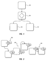
One property that is used in the examples illustrated herein is the OutgoingEdges property. This property defines the number of edges leaving a shape. In the present example, values of this property may be: 0, 1, or n, where n is a positive integer number. This property may have a default value assigned, such as 0, 1 or some other default value. Examples are illustrated in FIG. 1. FIG. 1 illustrates a source block or node 102, a decision block or node 104, and three activity blocks or nodes 106, 108 and 110. An OutgoingEdges property for the source node 102 may specify a property value of 1. An OutgoingEdges property for the decision node 104 may specify a property value of 3. An OutgoingEdges property for each of the activity nodes may specify property values of 0.
Another property that is used in the examples illustrated herein is the IncomingEdges property. This property defines the number of edges entering a shape. In the present example, values of this property may be: 0, 1, or n, where n is a positive integer number. This property may have a default value assigned, such as 0, 1 or some other default value. In the example illustrated in FIG. 1, each of the nodes, except the source node 102, may have an IncomingEdges property value of 1. The source node 102 may have an IncomingEdges property value of 0.
Another property that is used in the examples illustrated herein is the Depth property. This property defines the depth in the tree relative to a root node. In some embodiments, this property applies to directed diagrams only. For example, this property may apply to directed graphs. In the present example, values of this property may be any integer. The default value of this property may be any integer.
Another property that is used in the examples illustrated herein is the Orientation property. This property defines the current orientation of the shape or diagram.
Another property that is used in the examples illustrated herein is the IsRotated property. This property defines rotation state relative to parent node. In the present example, values of this property may be: TRUE or FALSE. If the property value is TRUE, then a node to which the property applies is rotated in “horse” fashion relative to a parent node. The default value of this property is False in this example.
Another property that is used in the examples illustrated herein is the IsSource property. This property specifies if the node is a source. In the present example, values of this property may be: TRUE or FALSE. If the property value is TRUE, then node is a source. The default value of this property is NULL in this example. For example, in FIG. 1, the source node 102 may have an IsSource property value of TRUE, while the other nodes 104-110 have IsSource vales of FALSE.
Another property that is used in the examples illustrated herein is the RelativeTop property. This property specifies position of node relative to an associated node with respect to top-bottom arrangement, based on the center point of the two nodes. In the present example, values of this property may be: 1, 0, ?1. If the value of this property is 1, the node to which it applies has a higher Y coordinate than the associated node. An example of this is illustrated by diagram 202 in FIG. 2. If the value of this property is ?1, the node to which it applies has a lower Y coordinate than the associated node. An example of this is illustrated at diagram 204 in FIG. 2. If the value of this property is 0, then the node to which it applies has the same Y coordinate as the associated node. An example of this is illustrated by diagram 206 in FIG. 2. The default value of this property is NULL in this example. FIG. 2 illustrates examples of behaviors for different values for the RelativeTop property.
Another property that is used in the examples illustrated herein is the RelativeLeft property. This property is similar to the RelativeTop property, but with respect to left-right arrangement. In the present example, values of this property may be: 1, 0, ?1. If this property has a value of 1, then the relevant node's X is greater than an associated node. An example of this is illustrated at 302. If this property has a value of ?1, then the relevant node's X is less than associated node. An example of this is illustrated at 304 in FIG. 3. If this property has a value of 0, then the relevant node's X is equal to an associated node. An example of this is illustrated at 304 in FIG. 3. The default value for this property in the present examples is NULL.
Example pattern triggers are illustrated below. These are only representative and by no means exhaustive.
百度 许勤强调,大力推进全面从严治党,一要旗帜鲜明讲政治。
<LayoutTrigger Name=”Decision”
?OutgoingEdges=”0..n” IncomingEdges=”0..1” IsSource=”True”
RelativeTop=”? 1”>
?<Setter Property=”SourceSide” Value=”Bottom” />
?<Setter Property=”SinkSide” Value=”Top” />
?<Setter Property=”ConnectionStyle” Value=”Curved” />
?<Setter Property”ConnectionVariant” Value=”Merged” />
</LayoutTrigger>

The preceding pattern trigger results in the diagram illustrated in FIG. 4. Another example is illustrated as:
<LayoutTrigger Name=”Decision”
?OutgoingEdges=”0..n” IncomingEdges=”0..1” IsSource=”True”
RelativeTop=”? 1”>
?<Setter Property=”SourceSide” Value=”Left” />
?<Setter Property=”SinkSide” Value=”Top” />
?<Setter Property=”ConnectionStyle” Value=”Curved” />
</LayoutTrigger>

The preceding code results in the example illustrated in FIG. 5.
Any pattern that is constructed by the user can be saved and then reused in other diagrams or at different locations in the same diagram. As such it is safe to view patterns as isolated units that can be reused within the same context or be taken out of their original context and placed in a new context.
Patterns can be combined together to create higher-order patterns. For instance, users could take the above connection routing pattern and reuse it in a pattern that dictates shape alignment. Consider the following example which uses patterns defined previously as a field in a new pattern:
<MultiLayoutTrigger RelativeLeft=”0”>
?<PatternReference PatternName=”Decision” />
?<Setter Property=”Alignment” Value=”CenterRelativeToParent” />
</MultiLayoutTrigger>
Just as patterns can be combined, they can also be applied separately to the same situation. For instance, the above pattern could have been broken down into two patterns, each for handling a different aspect of a diagram, one for handling line routing and the other for shape alignment. This is useful in complex diagrams where breaking down the patterns application helps the author deal with issues of scale.
On occasion pattern definitions will cause conflicts. For instance two or more patterns may match but “trigger” conflicting diagram layouts. Considering the above examples, pattern 1 could state . . .
<MultiLayoutTrigger RelativeLeft=”0”>
?<PatternReference PatternName=”Decision” />
?<Setter Property=”Alignment” Value=”CenterRelativeToParent” />
</MultiLayoutTrigger>

while pattern 2 could state . . .
<MultiLayoutTrigger RelativeLeft=”0”>
?<PatternReference PatternName=”Decision” />
?<Setter Property=”Alignment” Value=”LeftRelativeToParent” />
</MultiLayoutTrigger>
In such a case the system is able to fail gracefully. In one is example, a conflict is resolved by First “triggering” the last read pattern. Additionally embodiments may include functionality for surfacing an information message to the diagram layout system so that a visual or textual representation can be surfaced to the user.
The following discussion now refers to a number of methods and method acts that may be performed. It should be noted, that although the method acts may be discussed in a certain order or illustrated in a flow chart as occurring in a particular order, no particular ordering is necessarily required unless specifically stated, or required because an act is dependent on another act being completed prior to the act being performed.
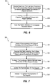
Referring now to FIG. 6, a method 600 is illustrated. The method included acts for defining a layout of diagram elements. The method includes receiving user input (act 602). The user input includes one or more declarative statements specifying conditional patterns based on attributes of diagram elements. The conditional patterns define layouts of diagram elements. Implementation of the layouts is dependent on conditions defined in the declarative statements and one or more values of one or more of the attributes. For example, in one embodiment a user may enter declarative statements into a command line user interface with the declarative statements specify the conditional patterns. An alternative embodiment, a user may use a wizard tool which outputs declarative statements specifying conditional patterns. Other alternatives may also be implemented.
The method 600 further includes organizing the conditional patterns as a pattern definition (act 604). For example, in one embodiment conditional patterns may be organized in a hierarchical format in a pattern definition to define how rules are applied.
The method 600 includes storing the pattern definition on a computer readable medium (act 606). The pattern definition is stored such that the pattern definition is retrievable by an application program that uses the pattern definition to evaluate the conditional patterns using values of attributes of one or more diagram elements. The application may be configured to display representations of the diagram elements according to the layouts when conditions for implementing the layouts are satisfied. For example, as discussed previously, an application may determine that a diagram is of a particular layout type. For example, a diagram may be a model type, a workflow instance, or a workpad instance. In one example, when an application determines that a diagram is, for example, a model type, then the application may consult the conditional patterns in the pattern definition to determine that elements should be oriented in a particular direction, that elements should be displayed to the right or left of other elements, that elements should be displayed above or below other elements, and/or that connectors, such as lines, and should extend from certain portions of elements.
As noted above, storing the pattern definition on a computer readable medium may include storing the pattern definition in a hierarchy of pattern definitions. In one embodiment, by storing the pattern definition in the hierarchy, the pattern definition can be used to implement diagram element layouts in the absence of other layout configuration information. In particular, if a parameter for a diagram layout pattern has not been defined, then a top or higher level pattern can be used to define a layout for elements of a diagram.
Referring now to FIG. 7, another example is illustrated. FIG. 7 illustrates a method 700 that may be practiced in a computing environment. The method 700 includes acts for facilitating defining a diagram layout. The method 700 includes displaying a representation of a diagram (act 702). The diagram includes one or more elements including one or more shapes or lines.
The method 700 further includes receiving user input (act 704). The user input includes one or more declarative statements specifying conditional patterns based on attributes of diagram elements. In one embodiment, a computing system may display a command line interface near the displayed representation of a diagram. A user can then enter declarative commands in the command line interface which are then applied to diagrams or diagram elements. In another embodiment, a computing system may display in a user interface declarative commands that are currently being used to define diagrammatic layout. The declarative commands may be editable, such that a user can insert or delete declarative commands, select portions of the commands to modify, and the like.
The method 700 further includes evaluating the conditional patterns using attributes of the one or more shapes or lines (act 706). For example, the conditional patterns may include information specifying shape type or diagram type. As noted, conditional patterns may specify decision diamonds or other shape types, workflows, or other diagram types, etc. The elements of the diagram can be evaluated against the specified shape type or diagram type.
The method 700 further includes updating the representation of the diagram based on evaluating the conditional patterns using attributes of the one or more shapes or lines (act 706) and displaying the updated representation of the diagram (act 706).
Embodiments of the method 700 may further include storing the one or more declarative statements as a pattern definition that can be applied to other diagrams. For example, the declarative statements may be stored in a data structure of a computer readable medium and used later for displaying representations of diagrams.
Reference in now made to FIG. 8, which illustrates a method 800 which may be implemented in another embodiment. The method 800 may be practiced in a computing environment and includes acts for displaying diagrams. In particular, the method may include acts for using stored pattern definitions or otherwise received definitions to display representations of diagrams and diagram elements. The method includes receiving one or more rules, the rules comprising one or more declarative statements specifying one or more conditional diagram layout patterns based on one or more attributes of diagram elements (act 802). The method 800 further includes evaluating the one or more rules using one or more attributes of one or more elements of a diagram (act 802). As noted, this may include evaluating such attributes as shape type, line type, diagram type, etc. Based on evaluating the one or more rules using one or more attributes of one or more elements of the diagram, a representation of the diagram is created (act 802) and the representation of the diagram is displayed (act 802).
Embodiments of the method 800 may be practiced where at least a portion of the one or more attributes of one or more elements of the diagram are contained in metadata about one or more elements of the diagram.
As noted, receiving one or more rules may include receiving a pattern definition including the one or more rules. In some embodiments, the pattern definition may be scoped to a particular layout type, model type, workflow instance, or workpad instance. In some embodiments, the pattern definition is a default pattern definition used in the absence of one or more other pattern definitions.
Notably, embodiments of the method 800 may be practiced where evaluating the one or more rules includes evaluating the pattern definition in conjunction with one or more additional pattern definitions. Each of the one or more additional pattern definitions includes one or more rules comprising one or more declarative statements specifying one or more conditional diagram layout patterns based on one or more attributes of diagram elements. When multiple pattern definitions are used, there is a chance for conflicts between the rules. Thus, some embodiments of the method 800 may further include detecting that the pattern definition conflicts with one or more of the additional pattern definitions and providing an indication to a user indicating that the pattern definition conflicts with one or more of the additional pattern definitions. In addition to and/or alternatively, embodiments may include provisions for resolving detected conflicts. For example, the method 800 may include resolving the detected conflict and selecting one of the pattern definition or one of the one or more additional pattern definitions to resolve the conflict. In one embodiment, resolving the detected conflict includes selecting a pattern definition that was read last in a multiple pattern definition.
The method 800 may also include selecting the pattern definition from among a number of pattern definitions specified for a given condition. The act of evaluating the one or more rules using one or more attributes of one or more elements of a diagram is performed as a result of selectively triggering the pattern definition. In other words, embodiments may be practiced where one pattern definition may be selected from among a number of different pattern definitions. In some embodiments, a user may be able to select a definition by declarative command, by interacting with a graphical user interface such as by selecting radio or check boxes or using pull-down menu selections, or with other user interfaces.
Embodiments of the present invention may comprise or utilize a special purpose or general-purpose computer including computer hardware, as discussed in greater detail below. Embodiments within the scope of the present invention also include physical and other computer-readable media for carrying or storing computer-executable instructions and/or data structures. Such computer-readable media can be any available media that can be accessed by a general purpose or special purpose computer system. Computer-readable media that store computer-executable instructions are physical storage media. Computer-readable media that carry computer-executable instructions are transmission media. Thus, by way of example, and not limitation, embodiments of the invention can comprise at least two distinctly different kinds of computer-readable media: physical storage media and transmission media.
Physical storage media includes RAM, ROM, EEPROM, CD-ROM or other optical disk storage, magnetic disk storage or other magnetic storage devices, or any other medium which can be used to store desired program code means in the form of computer-executable instructions or data structures and which can be accessed by a general purpose or special purpose computer.
A “network” is defined as one or more data links that enable the transport of electronic data between computer systems and/or modules and/or other electronic devices. When information is transferred or provided over a network or another communications connection (either hardwired, wireless, or a combination of hardwired or wireless) to a computer, the computer properly views the connection as a transmission medium. Transmissions media can include a network and/or data links which can be used to carry or desired program code means in the form of computer-executable instructions or data structures and which can be accessed by a general purpose or special purpose computer. Combinations of the above should also be included within the scope of computer-readable media.
Further, upon reaching various computer system components, program code means in the form of computer-executable instructions or data structures can be transferred automatically from transmission media to physical storage media (or vice versa). For example, computer-executable instructions or data structures received over a network or data link can be buffered in RAM within a network interface module (e.g., a “NIC”), and then eventually transferred to computer system RAM and/or to less volatile physical storage media at a computer system. Thus, it should be understood that physical storage media can be included in computer system components that also (or even primarily) utilize transmission media.
Computer-executable instructions comprise, for example, instructions and data which cause a general purpose computer, special purpose computer, or special purpose processing device to perform a certain function or group of functions. The computer executable instructions may be, for example, binaries, intermediate format instructions such as assembly language, or even source code. Although the subject matter has been described in language specific to structural features and/or methodological acts, it is to be understood that the subject matter defined in the appended claims is not necessarily limited to the described features or acts described above. Rather, the described features and acts are disclosed as example forms of implementing the claims.
Those skilled in the art will appreciate that the invention may be practiced in network computing environments with many types of computer system configurations, including, personal computers, desktop computers, laptop computers, message processors, hand-held devices, multi-processor systems, microprocessor-based or programmable consumer electronics, network PCs, minicomputers, mainframe computers, mobile telephones, PDAs, pagers, routers, switches, and the like. The invention may also be practiced in distributed system environments where local and remote computer systems, which are linked (either by hardwired data links, wireless data links, or by a combination of hardwired and wireless data links) through a network, both perform tasks. In a distributed system environment, program modules may be located in both local and remote memory storage devices.
The present invention may be embodied in other specific forms without departing from its spirit or essential characteristics. The described embodiments are to be considered in all respects only as illustrative and not restrictive. The scope of the invention is, therefore, indicated by the appended claims rather than by the foregoing description. All changes which come within the meaning and range of equivalency of the claims are to be embraced within their scope.

Claims (23)

What is claimed is:
1. A computer-implemented method of defining a layout of diagram elements, the method comprising:
a computer system, which includes a processor, receiving user input, the user input comprising one or more declarative statements specifying conditional patterns based on attributes of diagram elements, the conditional patterns defining layouts of diagram elements, wherein implementation of the layouts is dependent on conditions defined in the declarative statements and one or more values of one or more of the attributes;
the computer system organizing the conditional patterns as a pattern definition, wherein organizing the conditional patterns as a pattern definition comprises at least one of:
combining conditional patterns together to create a higher order pattern with a previously defined pattern being included in a new pattern as a definition field, or
breaking down a conditional pattern into the two or more patterns which are both applied to a same situation, but which define different aspects of a diagram; and
the computer system storing the pattern definition on a computer readable medium, wherein the pattern definition is stored such that the pattern definition is retrievable by an application program that uses the pattern definition to evaluate the conditional patterns using values of attributes of one or more diagram elements, the application further being configured to display representations of the diagram elements according to the layouts when conditions for implementing the layouts are satisfied.
2. The method of claim 1, wherein storing the pattern definition on a computer readable medium comprises storing the pattern definition in a hierarchy of pattern definitions.
3. The method of claim 2, wherein the pattern definition is stored in the hierarchy such that the pattern definition is used to implement diagram element layouts in the absence of other layout configuration information.
4. The method of claim 1, wherein at least one of the attributes of diagram elements comprises a layout type to which the diagram element belongs.
5. The method of claim 1, wherein organizing the conditional patterns as a pattern definition comprises combining the conditional patterns together to create one or more higher order patterns.
6. The method of claim 1, wherein organizing the conditional patterns as a pattern definition comprises breaking down the conditional patterns into the two or more patterns.
7. In a computing environment, a method of facilitating defining a diagram layout, the method comprising:
displaying a representation of a diagram, wherein the diagram comprises one or more elements including one or more shapes or lines;
displaying a command line interface that is operable to receive typed input comprising one or more declarative statements, the command line interface being displayed near the displayed representation of the diagram;
receiving user input at the command line interface, the user input comprising the one or more declarative statements specifying conditional patterns based on attributes of diagram elements;
evaluating the conditional patterns using attributes of the one or more shapes or lines;
updating the representation of the diagram based on evaluating the conditional patterns using attributes of the one or more shapes or lines; and
displaying the updated representation of the diagram.
8. The method of claim 7, further comprising storing the one or more declarative statements as a pattern definition that can be applied to other diagrams.
9. The method of claim 7, wherein receiving user input, the user input comprising one or more declarative statements specifying conditional patterns based on attributes of diagram elements comprises receiving conflicting user input, the method further comprising surfacing the conflict to the user.
10. The method of claim 7, wherein receiving user input, the user input comprising one or more declarative statements specifying conditional patterns based on attributes of diagram elements comprises receiving conflicting user input, the method further comprising resolving the conflict by using the last read user input.
11. In a computing environment, a method of displaying diagrams, the method comprising:
receiving one or more rules, the rules comprising one or more declarative statements specifying one or more conditional diagram layout patterns based on one or more attributes of diagram elements, wherein the one or more rules are scoped to either a particular use or particular hardware;
identifying the particular use or hardware that applies to a current situation for displaying a representation of a diagram;
selecting the one or more rules based on a determination that the one or more rules correspond to the current situation;
evaluating the one or more selected rules using one or more attributes of one or more elements of a diagram;
based on evaluating the one or more selected rules using one or more attributes of one or more elements of the diagram, creating a representation of the diagram; and
displaying the representation of the diagram.
12. The method of claim 11, wherein at least a portion of the one or more attributes of one or more elements of the diagram are contained in metadata about one or more elements of the diagram.
13. The method of claim 11, wherein receiving one or more rules comprises receiving a pattern definition including the one or more rules.
14. The method of claim 13, wherein the pattern definition is scoped to a particular layout type, model type, workflow instance, or workpad instance.
15. The method of claim 13, wherein the pattern definition is a default pattern definition used in the absence of one or more other pattern definitions.
16. The method of claim 13, wherein evaluating the one or more rules comprises evaluating the pattern definition in conjunction with one or more additional pattern definitions, wherein each of the one or more additional pattern definitions comprises one or more rules comprising one or more declarative statements specifying one or more conditional diagram layout patterns based on one or more attributes of diagram elements.
17. The method of claim 16, further comprising:
detecting that the pattern definition conflicts with one or more of the additional pattern definitions; and
providing an indication to a user indicating that the pattern definition conflicts with one or more of the additional pattern definitions.
18. The method of claim 17, further comprising resolving the detected conflict and selecting one of the pattern definition or one of the one or more additional pattern definitions to resolve the conflict.
19. The method of claim 18, wherein resolving the detected conflict comprises selecting a pattern definition that was defined read last in a multiple pattern definition.
20. The method of claim 13, further comprising selecting the pattern definition from among a plurality of pattern definitions specified for a given condition, and wherein evaluating the one or more rules using one or more attributes of one or more elements of a diagram is performed as a result of selectively triggering the pattern definition.
21. The method of claim 11, wherein the one or more rules are scoped to the particular use as well as the particular hardware, and such that the selection of the one or more rules includes selecting the one or more rules based on the particular use as well as the particular hardware that correspond to the current situation for displaying the representation of the diagram.
22. The method of claim 11, wherein the one or more rules include property definitions, the property definitions including at least a plurality of the following: an OutgoingEdges property, an IncomingEdges property, an IsRotated property, an IsSource property, a RelativeTop property, or a RelativeLeft property.
23. The method of claim 22, wherein the property definitions further include at least one of a Depth property or an Orientation property.
US12/271,699 2025-08-06 2025-08-06 Diagram layout patterns Expired - Fee Related US8453107B2 (en)

Priority Applications (2)

Application Number Priority Date Filing Date Title
US12/271,699 US8453107B2 (en) 2025-08-06 2025-08-06 Diagram layout patterns
US13/875,919 US8856730B2 (en) 2025-08-06 2025-08-06 Diagram layout patterns

Applications Claiming Priority (1)

Application Number Priority Date Filing Date Title
US12/271,699 US8453107B2 (en) 2025-08-06 2025-08-06 Diagram layout patterns

Related Child Applications (1)

Application Number Title Priority Date Filing Date
US13/875,919 Continuation US8856730B2 (en) 2025-08-06 2025-08-06 Diagram layout patterns

Publications (2)

Publication Number Publication Date
US20100125825A1 US20100125825A1 (en) 2025-08-06
US8453107B2 true US8453107B2 (en) 2025-08-06

Family

ID=42172965

Family Applications (2)

Application Number Title Priority Date Filing Date
US12/271,699 Expired - Fee Related US8453107B2 (en) 2025-08-06 2025-08-06 Diagram layout patterns
US13/875,919 Active US8856730B2 (en) 2025-08-06 2025-08-06 Diagram layout patterns

Family Applications After (1)

Application Number Title Priority Date Filing Date
US13/875,919 Active US8856730B2 (en) 2025-08-06 2025-08-06 Diagram layout patterns

Country Status (1)

Country Link
US (2) US8453107B2 (en)

Cited By (1)

* Cited by examiner, ? Cited by third party
Publication number Priority date Publication date Assignee Title
US9753620B2 (en) 2025-08-06 2025-08-06 Axure Software Solutions, Inc. Method, system and computer program product for facilitating the prototyping and previewing of dynamic interactive graphical design widget state transitions in an interactive documentation environment

Families Citing this family (2)

* Cited by examiner, ? Cited by third party
Publication number Priority date Publication date Assignee Title
US8453107B2 (en) 2025-08-06 2025-08-06 Microsoft Corporation Diagram layout patterns
US9405449B2 (en) * 2025-08-06 2025-08-06 Microsoft Technology Licensing, Llc Layout constraint manipulation via user gesture recognition

Citations (9)

* Cited by examiner, ? Cited by third party
Publication number Priority date Publication date Assignee Title
US6470482B1 (en) 2025-08-06 2025-08-06 Lsi Logic Corporation Method and system for creating, deriving and validating structural description of electronic system from higher level, behavior-oriented description, including interactive schematic design and simulation
US20050216883A1 (en) 2025-08-06 2025-08-06 Ishimitsu Michael K API for building semantically rich diagramming tools
US20060161890A1 (en) 2025-08-06 2025-08-06 Green Kenneth M Application-generic sequence diagram generator driven by a non-proprietary language
US20060209085A1 (en) * 2025-08-06 2025-08-06 Microsoft Corporation Providing 1D and 2D connectors in a connected diagram
US20060282830A1 (en) * 2025-08-06 2025-08-06 Microsoft Corporation Analysis of the impact of application programs on resources stored in data stores
US20070022399A1 (en) 2025-08-06 2025-08-06 Tian-Hau Tsai Rule-based schematic diagram generator
US7196712B2 (en) 2025-08-06 2025-08-06 Microsoft Corporation Dynamic, live surface and model elements for visualization and modeling
US20070300198A1 (en) 2025-08-06 2025-08-06 The Boeing Company Method for creating box level groupings of components and connections in a dynamic layout system
US20080189672A1 (en) * 2025-08-06 2025-08-06 Taiwan Semiconductor Manufacturing Company, Ltd. Method and System For a Pattern Layout Split

Family Cites Families (1)

* Cited by examiner, ? Cited by third party
Publication number Priority date Publication date Assignee Title
US8453107B2 (en) 2025-08-06 2025-08-06 Microsoft Corporation Diagram layout patterns

Patent Citations (9)

* Cited by examiner, ? Cited by third party
Publication number Priority date Publication date Assignee Title
US6470482B1 (en) 2025-08-06 2025-08-06 Lsi Logic Corporation Method and system for creating, deriving and validating structural description of electronic system from higher level, behavior-oriented description, including interactive schematic design and simulation
US7196712B2 (en) 2025-08-06 2025-08-06 Microsoft Corporation Dynamic, live surface and model elements for visualization and modeling
US20050216883A1 (en) 2025-08-06 2025-08-06 Ishimitsu Michael K API for building semantically rich diagramming tools
US20060161890A1 (en) 2025-08-06 2025-08-06 Green Kenneth M Application-generic sequence diagram generator driven by a non-proprietary language
US20060209085A1 (en) * 2025-08-06 2025-08-06 Microsoft Corporation Providing 1D and 2D connectors in a connected diagram
US20060282830A1 (en) * 2025-08-06 2025-08-06 Microsoft Corporation Analysis of the impact of application programs on resources stored in data stores
US20070022399A1 (en) 2025-08-06 2025-08-06 Tian-Hau Tsai Rule-based schematic diagram generator
US20070300198A1 (en) 2025-08-06 2025-08-06 The Boeing Company Method for creating box level groupings of components and connections in a dynamic layout system
US20080189672A1 (en) * 2025-08-06 2025-08-06 Taiwan Semiconductor Manufacturing Company, Ltd. Method and System For a Pattern Layout Split

Non-Patent Citations (2)

* Cited by examiner, ? Cited by third party
Title
Maier, Sonja and Mark Minas, "A Pattern-Based Layout Algorithm for Diagram Editors", Electronic Communications of the EASST vol. 7, 2007, pp. 1-16.
Minas, Mark, "Concepts and Realization of a Diagram Editor Generator Based on Hypergraph Transformation", Mar. 27, 2001, pp. 1-25.

Cited By (3)

* Cited by examiner, ? Cited by third party
Publication number Priority date Publication date Assignee Title
US9753620B2 (en) 2025-08-06 2025-08-06 Axure Software Solutions, Inc. Method, system and computer program product for facilitating the prototyping and previewing of dynamic interactive graphical design widget state transitions in an interactive documentation environment
US10275131B2 (en) 2025-08-06 2025-08-06 Axure Software Solutions, Inc. Facilitating the prototyping and previewing of design element state transitions in a graphical design environment
US10983678B2 (en) 2025-08-06 2025-08-06 Axure Software Solutions, Inc. Facilitating the prototyping and previewing of design element state transitions in a graphical design environment

Also Published As

Publication number Publication date
US8856730B2 (en) 2025-08-06
US20130246910A1 (en) 2025-08-06
US20100125825A1 (en) 2025-08-06

Similar Documents

Publication Publication Date Title
US9336184B2 (en) Representation of an interactive document as a graph of entities
KR101644418B1 (en) Visualizing relationships between data elements and graphical representations of data element attributes
US7089256B2 (en) Universal data editor
US7886028B2 (en) Method and system for system migration
US20120159333A1 (en) Representation of an interactive document as a graph of entities
WO2008060511A1 (en) Software development system and method for intelligent document output based on user-defined rules
US20140129550A1 (en) Content management
US20060150169A1 (en) Object model tree diagram
US9563861B2 (en) Integration of workflow and library modules
US20160267123A1 (en) Method for propagating information between a building information model and a specification document
US10031746B2 (en) Analyzing components related to a software application in a software development environment
CN101226559A (en) Method and computer program product of computer aided design of a product comprising a set of constrained objects
US8230357B2 (en) Visually processing instance data
US9031893B2 (en) Best match processing mode of decision tables
US20180005122A1 (en) Constructing new formulas through auto replacing functions
EP2770428A1 (en) Runtime process diagnostics
US8856730B2 (en) Diagram layout patterns
US8612892B2 (en) Incremental run-time layout composition
US20170300461A1 (en) Representation of an Interactive Document as a Graph of Entities
Basirati et al. Towards systematic inconsistency identification for product service systems
US8572551B2 (en) Difference log production for model merging
CN118778944A (en) A digital, low-code platform
CN113867700B (en) Model construction method, display platform, server and storage medium
Kannala Escape route analysis based on building information models: design and implementation
JP2006209179A (en) Model difference detection tool

Legal Events

Date Code Title Description
AS Assignment

Owner name: MICROSOFT CORPORATION,WASHINGTON

Free format text: ASSIGNMENT OF ASSIGNORS INTEREST;ASSIGNORS:DANTON, STEPHEN M.;SEHN, JORDAN C.;MURRAY, MICHAEL C.;AND OTHERS;SIGNING DATES FROM 20081112 TO 20081113;REEL/FRAME:021839/0455

Owner name: MICROSOFT CORPORATION, WASHINGTON

Free format text: ASSIGNMENT OF ASSIGNORS INTEREST;ASSIGNORS:DANTON, STEPHEN M.;SEHN, JORDAN C.;MURRAY, MICHAEL C.;AND OTHERS;SIGNING DATES FROM 20081112 TO 20081113;REEL/FRAME:021839/0455

FEPP Fee payment procedure

Free format text: PAYOR NUMBER ASSIGNED (ORIGINAL EVENT CODE: ASPN); ENTITY STATUS OF PATENT OWNER: LARGE ENTITY

STCF Information on status: patent grant

Free format text: PATENTED CASE

AS Assignment

Owner name: MICROSOFT TECHNOLOGY LICENSING, LLC, WASHINGTON

Free format text: ASSIGNMENT OF ASSIGNORS INTEREST;ASSIGNOR:MICROSOFT CORPORATION;REEL/FRAME:034564/0001

Effective date: 20141014

FPAY Fee payment

Year of fee payment: 4

MAFP Maintenance fee payment

Free format text: PAYMENT OF MAINTENANCE FEE, 8TH YEAR, LARGE ENTITY (ORIGINAL EVENT CODE: M1552); ENTITY STATUS OF PATENT OWNER: LARGE ENTITY

Year of fee payment: 8

FEPP Fee payment procedure

Free format text: MAINTENANCE FEE REMINDER MAILED (ORIGINAL EVENT CODE: REM.); ENTITY STATUS OF PATENT OWNER: LARGE ENTITY

LAPS Lapse for failure to pay maintenance fees

Free format text: PATENT EXPIRED FOR FAILURE TO PAY MAINTENANCE FEES (ORIGINAL EVENT CODE: EXP.); ENTITY STATUS OF PATENT OWNER: LARGE ENTITY

etf是什么意思 水中加什么擦玻璃干净 郡肝是什么部位 三点水弘读什么 修身养性下一句是什么
鸡蛋散黄是什么原因 姹什么嫣什么 冒昧打扰是什么意思 喜新厌旧是什么生肖 痔疮吃什么水果好得快
塞屁股的退烧药叫什么 鱼子酱为什么那么贵 子宫内膜厚是什么原因引起的 忌廉是什么东西 未曾谋面什么意思
何炅和谢娜是什么关系 强迫思维是什么 老年人便秘吃什么好 uhd是什么意思 5.8是什么星座
卡罗莱手表是什么档次hcv7jop9ns7r.cn 闭口长什么样子hcv8jop2ns7r.cn 两手发麻是什么原因hcv8jop4ns4r.cn 大便青黑色是什么原因hcv7jop9ns3r.cn 内膜增厚是什么原因hcv8jop3ns5r.cn
流产后吃什么食物hcv9jop3ns7r.cn 桑黄是什么hcv8jop8ns3r.cn 老当益壮是什么意思hcv9jop3ns7r.cn foreplay是什么意思hcv9jop1ns3r.cn 脸上出汗多是什么原因hcv7jop5ns4r.cn
咳嗽变异性哮喘吃什么药hcv9jop0ns0r.cn 董事总经理是什么职位aiwuzhiyu.com 李荣浩什么学历zsyouku.com 贫血到什么程度会晕倒hcv9jop7ns9r.cn 湿疹用什么药hcv9jop2ns7r.cn
爬山是什么意思hcv8jop9ns3r.cn 霸王别姬是什么菜hcv9jop8ns2r.cn 6d是什么意思hcv8jop8ns8r.cn 聿五行属什么hcv8jop8ns3r.cn 迥异是什么意思hcv9jop7ns4r.cn
百度