什么的草原| 612是什么星座| 绝对是什么意思| 侮辱什么意思| 小孩咬手指甲是什么原因| 天蝎是什么象星座| 王王是什么字| 为什么白天能看到月亮| 管状腺瘤是什么病| 真实的印度是什么样的| 自荐是什么意思| 龟毛的性格指什么性格| 产后第一次来月经是什么颜色| 脉滑是什么意思| 纳豆是什么豆子| 为什么喝中药会拉肚子| 上嘴角有痣代表什么| 什么木头做菜板好| 小孩晚上磨牙是什么原因引起的| 铁剂是什么| 火车动车高铁有什么区别| 红花油和活络油有什么区别| 孕妇吃什么水果好对胎儿好| 脖子痒是什么原因| 常温是什么意思| 四氯化碳是什么| 睡觉流口水是什么原因引起的| 肩周炎吃什么药效果最好| 鸡与什么生肖相合| EV是什么| 足交什么感觉| 马刺是什么| 孔雀为什么会开屏| 肠管积气是什么原因| 小腿发黑是什么原因| 扁桃体肿大有什么症状| 成都有什么大学| 忍者神龟是什么意思| 股骨头坏死什么症状| 长期开灯睡觉有什么危害| 蹭饭吃是什么意思| 狡黠什么意思| 马冬梅是什么电影| 下面干涩是什么原因导致的| egfr是什么| 包面是什么| 鼻炎是什么原因引起的| 纳米是什么意思| 什么民族不吃猪肉| 铁锈是什么颜色的| 涟漪是什么意思| fap什么意思| 两毛二是什么军衔| 血糖突然升高是什么原因| 医保自费是什么意思| 同人是什么意思| 鸟屎掉衣服上有什么预兆| 中性粒细胞百分比偏低是什么意思| 袍哥什么意思| 4月19号是什么星座| 鹿的部首是什么| 唇红齿白是什么生肖| 为什么丰胸霜一抹就变大| 孕妇为什么不能吃桃子| 孕妇吃鸡蛋对胎儿有什么好处| 犀利哥什么意思| 女人补铁有什么好处| 事不过三是什么意思| 凝血五项是检查什么的| 茜草别名又叫什么| 什么数码相机好| 脖子老出汗是什么原因| 家财万贯是什么生肖| 喉咙不舒服吃什么水果好| preparing是什么意思| ckd5期是什么意思| 缺钙查什么化验项目| 最大的荔枝是什么品种| 什么病不能吃西兰花| 肺结节吃什么药最好| 江西庐山产什么茶| 夏天为什么不能喝中药| 珑字五行属什么| 面部肌肉跳动是什么原因| 甲状腺一度肿大是什么意思| 吃什么最补肾| 易烊千玺的爸爸是干什么的| 房颤挂什么科| 奄奄一息的息是什么意思| 收缩压偏高是什么意思| 59岁属什么生肖| 总胆固醇是什么意思| 颈动脉b超是检查什么| 毛毛虫吃什么食物| 鸭肉和什么一起炖好吃| 不撞南墙不回头是什么意思| 脚痒是什么原因| 胃炎吃什么最好| 脉压是什么| 蓝灰色配什么颜色好看| 才高八斗是什么意思| 尿频挂什么科| 肠道易激惹综合征的症状是什么| 血淀粉酶是查什么的| 什么叫资本运作| kw是什么单位| 牛子是什么意思| mcg是什么意思| 定妆喷雾什么时候用| 话唠是什么意思| 102是什么意思| 官杀是什么意思| 黄金为什么值钱| 十二生肖它第一是什么生肖| 阑尾切除后有什么影响和后遗症| 伟五行属性是什么| 小寒是什么意思| 鸽子拉绿稀便是什么病| 商人是什么意思| 鼻窦炎吃什么抗生素| 印度什么时候独立的| 沙僧是什么动物| 怀孕吃什么水果比较好| 肌酸激酶高吃什么药| 清心寡欲下一句是什么| 宠物蛇吃什么食物| 戴帽子是什么意思| 活色生香什么意思| 大什么大| 什么食物补锌效果最好| 梦见自己杀人了是什么意思| 西门子洗衣机不脱水是什么原因| 骨质疏松吃什么好| 双氧水又叫什么名字| 什么病可以办低保| 为什么会出现彩虹| 斑鸠喜欢吃什么食物| 偶数是什么| 军师是什么意思| 榴莲不能和什么水果一起吃| 封面是什么意思| 口苦是什么原因造成的| 大脑记忆力下降是什么原因| 糖尿病人不能吃什么| 俊俏是什么意思| 懒趴是什么意思| 凝胶是什么| 精液什么颜色正常| cp是什么意思| 白醋和陈醋有什么区别| 舌头生疮是什么原因引起的| 吃榴莲有什么好处和坏处| 右手小指戴戒指什么意思| 胃出血恢复期吃什么好| 例假期间吃什么好| 三叉戟是什么意思| 方兴未什么| 不什么其烦| 自变量是什么| 诸葛亮为什么气死周瑜| 梦见自己结婚了是什么征兆| 怀孕脚浮肿是什么原因引起的| 做梦飞起来了是什么兆头| 农历正月是什么星座| 胃灼热烧心吃什么药| ppt是什么意思| 处女女和什么星座最配| 霸道总裁是什么意思| 手足口病忌口什么食物| 经常射精有什么伤害| 化疗恶心吃什么可以缓解| 尖锐湿疣吃什么药| 吃什么利尿最快去腹水的| 感染性发热是什么意思| 耳朵后面痒是什么原因| 喉炎雾化用什么药| 口腔炎吃什么药| spank是什么意思| 跳蚤最怕什么东西| 孔雀蓝配什么颜色好看| 蓝莓泡酒有什么功效| 颈椎压迫手麻吃什么药| 懿是什么意思| 四点底与什么有关| 遥字五行属什么| 鸡为什么吃自己下的蛋| 扶正固本是什么意思| 马步鱼为什么是甜的| 骨质疏松吃什么| clarks是什么牌子| 看膝盖挂什么科| 皮脂腺痣是什么原因引起的| 运钞车押运员是什么人| 血常规查的是什么项目| 炒作是什么意思| 爱出油的人身体缺什么| 蛇什么时候出来活动| 乳腺实性结节是什么意思| 宝宝病毒感染吃什么药效果好| 脾主四肢是什么意思| 高丽参有什么功效| 熠字五行属什么| 喝陈皮水有什么好处| 怀孕分泌物是什么颜色| 老公护着家人说明什么| 梦见离家出走是什么意思| 口干口苦口臭是什么原因引起的| 体积是什么意思| 拿什么让你幸福| 头自动摇摆是什么原因| 夜明珠代表什么生肖| 梦见自己掉牙是什么意思| 为什么会下雨| 忽必烈和成吉思汗是什么关系| 基围虾不能和什么一起吃| 30年婚姻是什么婚| 单核细胞高是什么原因| 嗓子疼可以吃什么水果| 2021年是什么年| 回奶是什么意思| 手为什么会长水泡| 为什么会有白带| 胸胀疼是什么原因| 排便困难用什么药| 足癣用什么药| 口字旁的字和什么有关| 胱抑素c高是什么原因| ou是什么意思| 下午17点是什么时辰| 开除是什么意思| 闰月年有什么讲究| 中耳炎用什么药最好| 茜字五行属什么| 人造珍珠是什么材质| 子宫内膜双层什么意思| 如常所愿是什么意思| 前列腺肥大是什么症状| 小米粥和什么搭配最好最养胃| 平均血小板体积偏高是什么原因| 胸闷气短挂什么科室| 低血压高是什么原因| 唱反调是什么意思| 甜叶菊有什么功效| 喉咙干咳吃什么药| 早上八点是什么时辰| 12月29号是什么星座| 彗星是什么| hermes是什么意思| 08年是什么年| 马来西亚人为什么会说中文| 天蝎座和什么座最配对| 只是女人容易一往情深是什么歌| 羊配什么生肖最好| 查询电话号码拨打什么| 章子怡是什么脸型| 孕妇宫缩是什么症状| 什么东西有头无脚| 化疗与放疗有什么区别| 黄瓜是绿色的为什么叫黄瓜| 焦急的什么| 吃什么才能提高免疫力| 减肥的原理是什么| xanax是什么药| wonderful什么意思| 百度

市委把全国两会精神原汁原味传达到基层

Difference log production for model merging Download PDF

Info

Publication number
US8572551B2
US8572551B2 US12/339,706 US33970608A US8572551B2 US 8572551 B2 US8572551 B2 US 8572551B2 US 33970608 A US33970608 A US 33970608A US 8572551 B2 US8572551 B2 US 8572551B2
Authority
US
United States
Prior art keywords
region
difference
sese
hierarchy
model
Prior art date
Legal status (The legal status is an assumption and is not a legal conclusion. Google has not performed a legal analysis and makes no representation as to the accuracy of the status listed.)
Expired - Fee Related, expires
Application number
US12/339,706
Other versions
US20090187881A1 (en
Inventor
Felix Feger
Christian Gerth
Jochen M. Kuester
Jussi H. Vanhatalo
Hagen Voelzer
Current Assignee (The listed assignees may be inaccurate. Google has not performed a legal analysis and makes no representation or warranty as to the accuracy of the list.)
International Business Machines Corp
Original Assignee
International Business Machines Corp
Priority date (The priority date is an assumption and is not a legal conclusion. Google has not performed a legal analysis and makes no representation as to the accuracy of the date listed.)
Filing date
Publication date
Application filed by International Business Machines Corp filed Critical International Business Machines Corp
Assigned to INTERNATIONAL BUSINESS MACHINES CORPORATION reassignment INTERNATIONAL BUSINESS MACHINES CORPORATION ASSIGNMENT OF ASSIGNORS INTEREST (SEE DOCUMENT FOR DETAILS). Assignors: VANHATALO, JUSSI H, FEGER, FELIX, GERTH, CHRISTIAN, KUESTER, JOCHEN M, VOELZER, HAGEN
Publication of US20090187881A1 publication Critical patent/US20090187881A1/en
Application granted granted Critical
Publication of US8572551B2 publication Critical patent/US8572551B2/en
Assigned to SERVICENOW, INC., INTERNATIONAL BUSINESS MACHINES CORPORATION reassignment SERVICENOW, INC. CONVEYOR IS ASSIGNING UNDIVIDED 50% INTEREST Assignors: INTERNATIONAL BUSINESS MACHINES CORPORATION
Expired - Fee Related legal-status Critical Current
Adjusted expiration legal-status Critical

Links

Images

Classifications

    • GPHYSICS
    • G06COMPUTING; CALCULATING OR COUNTING
    • G06FELECTRIC DIGITAL DATA PROCESSING
    • G06F8/00Arrangements for software engineering
    • G06F8/10Requirements analysis; Specification techniques

Definitions

  • This invention relates generally to the production of difference logs for use in merging of process models.
  • Methods, systems and computer programs are provided for producing a difference log which defines differences between process models in a data processing system.
  • Model-driven engineering is a technique employed in various engineering fields such as software, system and data engineering.
  • MDE involves the systematic use of models as primary engineering artifacts.
  • model-driven software development or model-driven business transformation relies on the use of models such as models defined in the Unified Modeling Language (UML).
  • UML Unified Modeling Language
  • a model merging scenario often arises where two or more models have to be brought together in some way.
  • One scenario for model merging is the improvement of an existing process model by a reference model, where some parts of the existing model should be preserved and others should be replaced.
  • Merging of process models is also required when different models need to be brought into some degree of conformity.
  • a simple example of this is the merging of business process models when companies are subject to acquisitions and mergers.
  • One aspect of the present invention provides a method for production in a data processing system of a difference log defining differences between process models defined in memory of the system.
  • the method comprises:
  • difference log defining said differences in the memory, the difference log indicating, for each difference, a region of at least one of said SESE region hierarchies in which that difference occurs.
  • a difference log defining differences between process models can be produced automatically based on representations of the process model structure as a hierarchy of SESE regions.
  • region comparison data is provided in addition to model comparison data which defines correspondences between elements of the models. This defines correspondences between regions of the SESE region hierarchies for the models.
  • model comparison data which defines correspondences between elements of the models
  • region comparison data is provided in addition to model comparison data which defines correspondences between elements of the models.
  • region comparison data is provided in addition to model comparison data which defines correspondences between elements of the models.
  • region comparison data is provided in addition to model comparison data which defines correspondences between elements of the models.
  • regions comparison data which defines correspondences between regions of the SESE region hierarchies for the models.
  • any differences occurring in that region can be identified from the difference log and differences can be addressed on a region by region basis throughout the SESE region hierarchy.
  • Different categories of differences can be identified, for instance control flow differences can be identified as well as mere addition or deletion of model elements, and dependencies between differences that are important in process merging can be detected and dealt with accordingly.
  • this technique provides a basis for systematic resolution of differences which does not rely on the prior existence of a change log. Rather, the difference log corresponds in effect to one possible change log, and one which, by linking differences to the process model structure via the SESE regions, provides the basis for efficient and comprehensive difference resolution in process merging operations.
  • the log could indicate, directly or indirectly, one or more regions of one or more of the SESE region hierarchies to which that difference relates.
  • the difference log defines a hierarchy of regions corresponding to a combined SESE region hierarchy which combines the SESE region hierarchies for the models and is defined by combined hierarchy data in the memory.
  • Each difference is then indicated in the region of the difference log hierarchy corresponding to the region of the combined SESE region hierarchy in which that difference occurs.
  • the region of a given SESE region hierarchy in which a difference occurs can be indicated simply by inclusion of that difference in the region of the difference log hierarchy corresponding to the appropriate combined hierarchy region.
  • a structured difference log is produced, the difference log having a hierarchical structure corresponding to the structure of the process models. This provides an efficient difference representation which can be displayed to a user for convenient, user-friendly visualization and resolution of differences as discussed further below.
  • Methods embodying the invention preferably include, in response to user input indicating a region of a said SESE region hierarchy, identifying from the difference log any differences associated with that region, and producing a difference display displaying those differences to the user.
  • associated differences here could be those indicated by the log as occurring in the user-specified region and/or those occurring in the corresponding region(s) of the or each other SESE region hierarchy.
  • the difference display in response to a user input indicating a region of a SESE region hierarchy, any differences indicated in the corresponding region of the difference hierarchy can be identified and displayed in the difference display.
  • the difference display preferably includes a representation of the user-specified SESE region plus a representation of any corresponding region(s) of the or each other SESE region hierarchy.
  • Embodiments can be envisaged in which the combined hierarchy data has been previously generated and stored in memory for the process models in question.
  • the process of difference log production may include processing the region comparison data and the model structure data for the models to generate the combined hierarchy data.
  • the region comparison data for the process models may have been previously generated and stored in memory in some embodiments.
  • the difference log production process may include the steps of comparing regions of the SESE region hierarchies defined by the model structure data to detect the correspondences between regions, and generating the region comparison data defining those correspondences.
  • the model structure data defining the SESE region hierarchies has been previously generated for the models.
  • the model structure data which defines the SESE region hierarchy could be the fundamental model definition in the system.
  • the difference log production process may include the steps of analyzing a model defined in system memory to detect hierarchical SESE regions thereof, and generating the model structure data defining the SESE region hierarchy for that model. This may be done for one or more of the models as required.
  • the model comparison data be updated after generation of the region comparison data to include any new correspondences between elements of corresponding regions of the two models. This will be discussed further below.
  • the model structure data for that model can be updated accordingly and the difference log updated to eliminate that difference.
  • the update process here can involve updating correspondences between model elements and/or SESE regions as required.
  • Preferred embodiments include various additional features to facilitate merging operations. For example, embodiments can suggest insertion points in a SESE region hierarchy for hierarchy elements which need to be moved or inserted to resolve a difference between the models. Embodiments can also filter identified differences, such as differences relating to control action node elements, to eliminate differences which are not of interest to the merging operation. These techniques will be discussed further below.
  • a second aspect of the invention provides a computer program comprising program code means for causing a data processing system to perform a method according to the first aspect of the invention.
  • data processing system is used here in the most general sense and includes any device, component or distributed system which has a data processing capability for implementing a computer program.
  • Such a computer program may thus comprise separate program modules for controlling different components of a distributed system where provided.
  • a computer program embodying the invention may constitute an independent program or may be a component of a larger program, and may be supplied, for example, embodied in a computer-readable medium such as a disk or an electronic transmission for loading in a computer system.
  • the program code means of the computer program may comprise any expression, in any language, code or notation, of a set of instructions intended to cause data processing system to perform the method in question, either directly or after either or both of (a) conversion to another language, code or notation, and (b) reproduction in a different material form.
  • a third aspect of the invention provides a system for producing a difference log defining differences between process models.
  • the system comprises:
  • model structure data defining a hierarchy of SESE regions representing the structure of that model
  • model comparison data defining correspondences between elements of the models
  • region comparison data defining correspondences between regions of the SESE region hierarchies for the models
  • control logic adapted to analyze the model comparison data and the region comparison data to identify differences between the SESE region hierarchies, and to produce and store in the memory a difference log defining said differences, the difference log indicating, for each difference, a region of at least one of said SESE region hierarchies in which that difference occurs.
  • FIG. 1 is a schematic representation of a modeling system incorporating a difference log production system embodying the invention
  • FIG. 2 is a flow chart illustrating key steps in operation of the difference log production system
  • FIG. 3 illustrates decomposition of a process model into SESE regions
  • FIG. 4 illustrates a process structure tree representing the hierarchy of SESE regions in FIG. 3 ;
  • FIG. 5 shows SESE regions of two models illustrating region matching considerations
  • FIG. 6 shows a difference display produced by the FIG. 1 system illustrating an inter-region control flow difference
  • FIG. 7 shows another difference display illustrating a complex control flow difference
  • FIG. 8 shows a further difference display illustrating a control flow difference within a sequential SESE region
  • FIG. 9 shows an example of corresponding SESE regions used in explaining an insertion point identification technique employed in the FIG. 1 system
  • FIGS. 10 and 11 show examples of corresponding SESE regions using in explaining a difference filtering technique employed in the FIG. 1 system.
  • FIG. 12 illustrates corresponding SESE regions in a scenario where adjustment of correspondences is performed in the FIG. 1 system.
  • SESE regions originated in work on compiler theory and are discussed in: “The Program Structure Tree: Computing control regions in linear time”, R. Johnson, D. Pearson, and K. Pingali, Proceedings of the ACM SIGPLAN'94 Conference on Programming Language Design and Implementation, pages 171-185, June 1994; and “Faster and More Focused Control-Flow Analysis for Business Process Models through SESE Decomposition”, J. Vanhatalo, H. V?lzer, and F. Leymann, LNCS 4749, pp. 43-45, Springer September 2007.
  • SESE region is a defined subset of the set of elements and their interconnecting edges which make up the structure of a model as will be explained in more detail below.
  • FIG. 1 is a schematic representation of a modeling system, indicated generally at 1 , showing the main components involved in the difference log production process.
  • the system 1 is implemented by specialized software running on a general-purpose computer with the usual user interfaces for input and display.
  • the main components of system 1 are represented generally in the figure by memory 2 and a difference log generator 3 .
  • the difference log generator 3 includes components indicated as a model analyzer 4 , a region matcher 5 and a difference analyzer 6 .
  • the system memory 2 stores various information for operation of the system, including process models A and B, defined by respective software modules, and model comparison data “Comp M ” for the two models as described below.
  • the memory 2 also holds various other data generated in operation of the system.
  • the difference log generator 3 comprises control logic for implementing the difference log production process described below. In general, this control logic could be implemented in hardware, software or a combination thereof. In this embodiment, however, the difference log generator logic is implemented by software running on computer system 1 , with respective software modules providing the model analyzer 4 , region matcher 5 and difference analyzer 6 . Suitable software will be apparent to those skilled in the art from the description of operation herein.
  • the difference log production is described below in relation to merging of two process models A and B.
  • the model merging process utilizes model comparison data in the form of comparison file Comp M which defines correspondences between elements of the two models.
  • Various systems are known for defining correspondences between model elements, for example as described in the documents referenced earlier.
  • the preferred embodiment described here employs the correspondence system disclosed in the reiterater et al. references above. Briefly, using this system the comparison Comp M can include different types of correspondences such as a 1-1 correspondence, a 1-0 correspondence and a 0-1 correspondence described earlier. Further correspondences include the 1-many (1-m) correspondence and the many-1 (m-1) correspondence which specify that a single element of one model corresponds to a number of elements in the other model.
  • the comparison Comp M can be derived as a correspondences file for the models specifying the identities of corresponding elements in the two models.
  • the particular way in which this comparison is derived is not central to the present invention and need not be described here. It suffices that such a comparison defining correspondences between the model elements is provide in memory 2 for use in generation of the difference log.
  • Step 10 of this figure represents generation of the model structure data defining the SESE region hierarchies for models A and B. This step is performed by model analyzer 4 of difference log generator 3 based on analysis of the model definitions in memory 2 . The process of generating the SESE region hierarchies is described in more detail below with reference to FIGS. 3 and 4 .
  • Step 11 of FIG. 2 represents generation of the region comparison data Comp R . This step is performed by region matcher 5 of difference log generator 3 and essentially involves comparing regions of the SESE region hierarchies to identify corresponding, or “matching”, regions in the two hierarchies. The result of this process is a region comparison file Comp R , similar to the model comparison file Comp M , but defining the identified correspondences between regions of the two SESE region hierarchies. The region matching process will be discussed in more detail below.
  • Step 12 of FIG. 2 represents the core of the difference log generation process. This is performed by the difference analyzer 6 of difference log generator 3 and involves analysis of the model comparison file Comp M and the region comparison file Comp R to identify differences between the SESE region hierarchies for the models. This step involves identification of various different categories of differences as discussed in more detail below.
  • the identified differences are stored in the form of a hierarchical difference log structure in system memory 2 .
  • the hierarchical structure of the difference log reflects the hierarchical structure of the process models.
  • the difference log structure is based on a combined SESE region hierarchy which combines the SESE region hierarchies for the two models. Generation of the combined hierarchy will be described further below.
  • differences are associated with the regions of the model region hierarchies in which they occur by indicating each difference in the appropriate region of the combined hierarchy structure.
  • the difference log also records, for each region of the difference hierarchy, the basic structure of the corresponding region(s) of the two model region hierarchies. This provides the basis for an exceptionally user-friendly difference display as demonstrated below.
  • differences are recorded in the difference log by difference analyzer 6 in the form of an instruction or operation to be performed to resolve that difference. For example: a difference concerning a missing element x might be expressed as “add element x”; a difference relating to reordering of elements might be expressed as “move element y”, and so on.
  • Difference analyzer 6 also performs various subsidiary tasks such as identification of possible insertion points for elements to be added or moved, and filtering of identified differences relating to control action nodes. These tasks will be discussed further below.
  • differences can be displayed to a user who can interact with the system to modify the models to eliminate differences.
  • This process is represented by step 13 of FIG. 2 .
  • the user can call up a difference display displaying the contents of the difference log corresponding to any region of the SESE region hierarchies.
  • a user can input any region of either hierarchy, and the system will display the contents of the corresponding region of the difference log hierarchy.
  • the difference display also includes a representation of the corresponding regions of the two model hierarchies. The user can thus navigate through the hierarchical model structure, viewing the corresponding regions of the difference log, and can equally navigate through the difference log hierarchy viewing the relevant structure of the two process models.
  • the difference display produced by difference log generator 3 will be illustrated by examples below.
  • the user can modify either model as required to eliminate differences.
  • the user can, for example, select a hierarchy region and resolve all differences within that region.
  • the model analyzer 4 in response to user input changing a model, can update the SESE region hierarchy representation accordingly, and the difference analyzer 6 can update the difference log to reflect the change.
  • the difference analyzer 6 will also update the correspondence files Comp M and Comp R to reflect any altered correspondences.
  • the process model in FIG. 3 has more regions than those that are shown explicitly.
  • the union of the regions J and K, denoted J ? K, as well as K ? L are also regions. These, however, are not interesting to us and they are subsumed in region X. Interesting regions will be called “canonical” as defined in the following.
  • two regions R and R′ are in sequence if the exit edge of R is the entry edge of R′ or vice versa.
  • the union R ? R′ of two regions R and R′ that are in sequence is a region again.
  • the regions shown in FIG. 3 are exactly the canonical regions of that process model. Since canonical regions are the most interesting for our purposes, only canonical regions are considered in the preferred system of FIG. 1 . In the following description of operation, therefore, we will mean ‘canonical region’ whenever we say ‘region’.
  • model analyzer 4 calculates the SESE regions as defined above using known techniques of compiler theory as detailed in the references given earlier. Since canonical regions do not overlap but are either nested or disjoint, it is possible to organize the canonical regions in a unique tree. We call this tree the “process structure tree” of a process model. This process structure tree is computed by model analyzer 4 in this embodiment as a convenient representation of the SESE region hierarchy of a model. The process structure tree can be computed in time linear in the size of the process model.
  • FIG. 4 shows the process structure tree representing the region hierarchy of the process model from FIG. 3 . A region is represented as a boxed tree node.
  • nodes of the process model are represented for convenience as leaves in the tree.
  • the parent of a region R (being a process model node n) is the smallest region R′ that contains R (node n).
  • R is a child region of R′ (n is a child node of R′).
  • the process structure trees representing the SESE region hierarchies for models A and B are stored in memory 2 .
  • Region matcher 5 then analyzes these hierarchies, performing a region matching process to identify corresponding (matched) regions in the two hierarchies. Basically this process involves comparing regions of the two hierarchies and applying some predefined matching strategy to determine whether regions are matching or not.
  • Various matching strategies could be employed as desired here, but in the following we describe an exemplary matching strategy which can be applied by region matcher 5 .
  • FIG. 5 illustrates the SESE region matching problem. It shows four SESE regions that have been identified in two process models A and B. However, identifying the SESE regions in both process models does not automatically establish a connection between regions in the two models.
  • identifying the SESE regions in both process models does not automatically establish a connection between regions in the two models.
  • this strategy for matching one could consider two regions to be matched if they contain corresponding entry and exit elements. For example, in FIG. 5 , this strategy would indicate a match if the control action nodes (i.e. decision, merge) have 1-to-1 correspondences in the file Comp M and have not been deleted and recreated. However, if the latter condition is not satisfied, the strategy will not lead to a matching. In such a case, one might consider a matching based on the enclosed elements.
  • We first describe a number of different strategies for matching and then explain a comprehensive strategy adopted in this embodiment:
  • Strategy S 1 Given a region R 1 and a region R 2 , they are considered to be matching if they have corresponding entry and exit nodes.
  • Strategy S 2 Given a region R 1 and a region R 2 , they are considered to be matching if they have a corresponding entry or exit node.
  • Strategy S 3 Given a region R 1 and a region R 2 , they are considered to be matching if they have corresponding elements inside.
  • Strategy S 4 Given a region R 1 and a region R 2 , they are considered to be matching if they contain regions R 3 and R 4 which are matching.
  • a combination of individual strategies is required as only one strategy will lead to bad results.
  • strategy S 1 individually will lead to lots of unmatched regions if control nodes are deleted and recreated.
  • the comprehensive strategy employed by region matcher 5 in this embodiment involves the following steps: 1. Given a set of regions R, we compute a matching according to S 4 . If we get more than one candidate, we apply strategy S 3 . We remove all matched regions from the set of regions R. 2. Given a set of regions R, we compute a matching according to S 3 . If we get more than one candidate, we apply strategy S 1 and S 2 . We remove all matched regions from the set of regions R. 3. Given a set of regions R, we compute a matching according to S 2 . We remove all matched regions from the set of regions R.
  • region matcher 5 Given a set of regions R, we compute a matching according to S 1 . We remove all matched regions from the set of regions R. This strategy first searches for matching regions based on already matched regions within the candidates and based on matching elements inside the regions. Suitable algorithms for implementing this strategy in region matcher 5 will be apparent to those skilled in the art.
  • the result of the region matching process is the region correspondences file Comp R defining the matched regions of the two SESE region hierarchies. After this process, region matcher 5 may update the model element correspondences file Comp M to include any new correspondences resulting from matching of SESE regions. This will be described further below.
  • the core difference log generation process is performed by difference analyzer 6 in step 12 of FIG. 2 .
  • difference analyzer 6 processes the individual region hierarchies for models A and B in conjunction with the region correspondences file Comp R to generate combined hierarchy data defining this combined SESE region hierarchy.
  • the combined hierarchy is represented in the form of a combined SESE tree which is generated from the individual process structure trees for models A and B in accordance with the following process.
  • SESE TREE V 1
  • SESE TREE V 2
  • correspondences between their nodes defined by the correspondence file Comp R V 1
  • SESE TREE V 2
  • V ? V maps a node ? V to its father in the SESE tree.
  • the combined SESE tree can be constructed as follows:
  • difference analyzer 6 can generate the hierarchical difference log by identifying and recording differences occurring in the various regions of the combined SESE hierarchy. That is, a difference occurring in a region of one of the two model region hierarchies, say the model A hierarchy, is recorded in the difference log for the region of the combined SESE region hierarchy which corresponds to that model A region. In this embodiment, this is performed by enriching the nodes of the combined SESE structure tree with the identified differences. This is done as follows for differences expressed by operational instructions “Move”, “Delete” and “Insert” as discussed further below:
  • difference is associated with the node representing the region in which difference takes place;
  • difference is associated with the node representing the region into which the element is moved and the node representing the region out of which the element is moved;
  • difference is associated with the node in SESE TREE (V 1 , V 2 ) representing this region.
  • the resulting difference log represents, in effect, one possible change log for the two process models. Differences are identified by analyzing the model and region correspondences files Comp M and Comp R for various different categories of differences. The difference analyzer can distinguish between the following types of differences that can occur:
  • a difference between two corresponding model elements occurs if attributes of a task or subprocess have been changed.
  • Category 1 differences occur if model elements such as tasks or subprocesses are deleted or added to one of the models.
  • Category 2 differences deal with the situation that tasks or subprocesses have been reordered.
  • Category 3 differences occur if parallel or alternative regions are added or deleted.
  • Difference analyzer 6 calculates Category 0 differences by comparing corresponding elements and then comparing each of the attributes.
  • Category 1 differences can be easily calculated: each 0-1 correspondence and 1-0 correspondence gives rise to such a difference.
  • Category 2 differences are calculated using two approaches: for control-flow changes within a SESE region, difference analyzer 6 uses a method described below. Control-flow changes across SESE regions can be detected by comparing elements of each SESE region that do not have 0-1 or 1-0 correspondences.
  • Category 3 differences are calculated simply by identifying newly inserted and deleted SESE regions. In the following, we elaborate on the calculation and visualization of Category 2 differences and Category 3 differences.
  • Category 2 differences can occur due to two changes: elements may have been moved from one region to another, and elements may have been moved within a region.
  • the former changes can be easily identified as follows. For each element in the primary model, e.g. model B, the corresponding element in the secondary model, model A, is identified from the Comp M file. For each element, the SESE region directly enclosing that element is identified from the corresponding region hierarchy. Difference analyzer 6 then determines from the Comp R file whether the two regions have been matched. If yes, the element in the secondary model A has not been moved to another region compared to primary model B, otherwise it has been moved. The following algorithm gives an implementation of this process.
  • FIG. 6 shows an example of the difference display displayed to a user for an inter-region control flow difference recorded in the difference log.
  • the task Task: 3 has been moved from R 2 ′ to R 1 ′. This is identified using the previous algorithm and visualized in the difference view as shown.
  • the upper section of the difference view displays a representation of the corresponding regions of the two models in which the difference occurs.
  • the lower section of the display displays the contents of the region of the hierarchical difference log structure corresponding to the relevant regions of the two models.
  • the central column gives details of the difference based on the structure of the combined region hierarchy described above. This indicates the difference in question in the form of an operational instruction “Move Task 3 ”.
  • difference analyzer 6 can also calculate and display an appropriate insertion point in the model structure for the element to be moved. This is done using a “fixpoint” technique which will be described later.
  • SESE regions are newly inserted or deleted. Newly inserted SESE regions can be identified because for those no matching partner in the primary model will be found, deleted SESE regions can be identified because for those no matching partner in the secondary model can be found.
  • the following pseudo code provides an implementation for calculating those complex control flow differences in difference analyzer 6 .
  • FIG. 7 shows an example of the difference display where a complex control flow difference occurs.
  • a new region an Alternative Region
  • difference analyzer 6 can calculate an insertion point for this alternative region using the fixpoint technique described below.
  • control flow difference occurring in a linear sequential SESE region is illustrated in the difference view of FIG. 8 .
  • differences can be identified by difference analyzer 6 in various ways based on analysis of predecessor and successor elements of a given element in the control flow. For example, given an element n in the primary model, its control flow conflicts are calculated as follows. First, its predecessors and successors in the primary model are calculated. Second, the predecessors and successors of the corresponding element n′ in the secondary model are calculated. Third, these sets are compared. If a node x is a predecessor in the primary model but a successor in the secondary model, this represents a control flow conflict.
  • difference analyzer 6 can detect changes to the control flow and express these as a set of operations to resolve the control flow conflicts. This is indicated in the difference view of FIG. 8 for the particular control flow difference illustrated.
  • fixpoints are used to determine the edges of a region in the primary process model, where an element has to be inserted or moved to, according to its position in the matching region in the secondary process model.
  • fixpoint An element x P of the primary process model is called fixpoint, if it has a corresponding element x S in the secondary process model and the following requirements are fulfilled:
  • the calculation of Fixpoints is divided into two steps: the calculation of a Fixpoint predecessor and the calculation of a Fixpoint successor.
  • the algorithm starts at the position of X in the secondary process model and examines the predecessors of X in reverse control flow order.
  • the first predecessor is element A, which fulfills all requirements of our definition of a Fixpoint, thus A is the Fixpoint predecessor of X.
  • the calculation of the Fixpoint successor of X is analogous to the calculation of the Fixpoint predecessor, except that the successors of X are examined in control flow order.
  • the Fixpoint successor of X is C. So X has to be inserted in the primary process model between A and C, in other words the edges (A-B) and (B-C) are possible insertion points.
  • the following algorithms calculate the Fixpoint predecessor and successor for a given element e.
  • FIG. 10 shows such an example.
  • a control action node element such as a decision, merge, fork or join node
  • FIG. 10 shows such an example.
  • the other merge and Decision represent newly inserted elements in process model A.
  • R 1 and R 2 are matched and that R 3 represents a newly inserted region.
  • control actions should be visualized as newly inserted elements or moved elements. This is the case if they are not entry or exit elements of a well-formed SESE region, such as in FIG. 11 .
  • the Decision: 3 has been newly inserted and it should be visualized as such an element. All the other elements should not be visualized as moved or newly inserted because they are first or last elements of SESE regions.
  • deleted control actions which are then created again, and which will lead to 1-to-0 and 0-to-1 correspondences in the comparison. If no additional actions are taken, they will be represented as deleted and inserted elements.
  • the decision whether to include a difference relating to a control action node in the difference log is dependent on whether that control action node and any corresponding element in the other SESE region hierarchy are boundary node elements, where a “boundary node element” here is an entry or exit node of a SESE region.
  • the difference analyzer applies the following basic rules for inclusion of control action changes in the difference log, and hence visualization of these changes in the difference display.
  • control action elements should be treated in a special way for change visualization. For a two-way merge of two process models, this is sufficient. However, there are scenarios where correspondences should be adjusted after region matching if control action changes have been made. This is explained in the following.
  • region matching is used to identify similar regions. This region matching is partially based on corresponding entry/exit nodes of two regions. We have explained that this strategy is not sufficient if control actions are deleted and recreated or if they are moved to other regions. In such cases, the result of region matching contains additional information that is not present in the correspondences. After process model merging, this additional information is lost if it is not encoded into correspondences. As a consequence, in merging scenarios where this additional information is important, correspondences should be adapted after region matching. Such a scenario is illustrated in FIG. 12 . Here, we assume that models V 1 and V 2 are derived independently from a model M. We further assume that during such derivations, the control action nodes in regions R 3 and R 4 are deleted and newly created.
  • R 2 will be matched with R 3 and R 4 when comparing M and V 1 and M and V 2 .
  • the transitive correspondences between these control action nodes will not be established (see the reference just mentioned for a detailed algorithm defining how this can be done).
  • region matching will not be able to match region R 3 and R 4 because they also do not contain any corresponding elements, as these have been deleted. As a consequence, a deleted and a newly inserted region will be displayed, which is not very useful.
  • the region matching information will be encoded into the correspondences. For example, if region R 2 in M is matched with region R 3 in V 1 , one could re-establish 1-to-1 correspondences for the entry/exit control actions.
  • the user can navigate through the difference log, viewing the difference display, and interact with the system to eliminate differences between the models.
  • the model analyzer 4 can update the SESE region hierarchy representation, and the difference analyzer 6 can update the difference log to reflect the change.
  • Difference analyzer 6 can also update the correspondence files Comp M and Comp R as necessary to reflect any altered correspondences resulting from merging operations.
  • the difference display generated from the structured difference log presents differences in a way that is particularly useful for the modeler, facilitating handling of large numbers of changes to large process models. When given a large process model, a long list of differences would be confusing.
  • system 1 displays differences in a structured way that is similar to the structure of the process model itself.
  • System 1 also facilitates a layered approach to resolving differences, whereby structural differences can be resolved first, then attribute differences can be dealt with. For this purpose, a new attribute difference display could be generated that focuses on displaying attribute differences for elements that have a 1-to-1 correspondence. Overall, therefore, it will be seen that system 1 provides a highly efficient tool for comprehensive difference resolution in process merging operations, and one which does not rely on the prior existence of a change log.

Landscapes

  • Engineering & Computer Science (AREA)
  • General Engineering & Computer Science (AREA)
  • Theoretical Computer Science (AREA)
  • Software Systems (AREA)
  • Physics & Mathematics (AREA)
  • General Physics & Mathematics (AREA)
  • Debugging And Monitoring (AREA)

Abstract

Methods and apparatus are provided for production of a difference log in a data processing system. The difference log defines differences between process models defined in system memory. For each of the process models, model structure data provided in memory defines a hierarchy of SESE regions representing the structure of that model. Also provided in memory are model comparison data defining correspondences between elements of the models, and region comparison data defining correspondences between regions of the SESE region hierarchies for the models. The model comparison and region comparison data are analyzed to identify differences between the SESE region hierarchies, and a difference log defining said differences is produced. In preferred systems, the model structure data and the region comparison data are computed for the models, and the difference log has a hierarchical structure corresponding to the structure of the process models.

Description

FIELD OF THE INVENTION
This invention relates generally to the production of difference logs for use in merging of process models. Methods, systems and computer programs are provided for producing a difference log which defines differences between process models in a data processing system.
BACKGROUND OF THE INVENTION
Model-driven engineering (MDE) is a technique employed in various engineering fields such as software, system and data engineering. MDE involves the systematic use of models as primary engineering artifacts. For example, model-driven software development or model-driven business transformation relies on the use of models such as models defined in the Unified Modeling Language (UML). When dealing with business process models for instance, a model merging scenario often arises where two or more models have to be brought together in some way. One scenario for model merging is the improvement of an existing process model by a reference model, where some parts of the existing model should be preserved and others should be replaced. Merging of process models is also required when different models need to be brought into some degree of conformity. A simple example of this is the merging of business process models when companies are subject to acquisitions and mergers. In such situations, processes have to be aligned at the business and IT level, while identifying and preserving differences where appropriate. Another merging scenario arises if two or more different versions of the same model need to be integrated. For example, where models are manipulated in a distributed manner by several modelers, changes made in different models must be consolidated at some point and an integrated, consolidated model created. Here, differences must be analyzed and parts of different copies must be merged into the integrated model.
Existing techniques and tools offer only limited support for process model merging. For example, most existing merging tools rely on existence of a log which records the changes that have been made to a model and thus provides an indication of differences which need to be addressed. Some prior work has proposed use of a comparison, consisting of correspondences between elements of two process models, as a basis for resolving some differences between process models by a model merging activity. For example, a technique for comparing models using different types of correspondences between model elements is disclosed in “Methodology and Tooling to combine an existing legacy business
process model with best-practice industry reference models for Business Transformation”, Jochen Küster et al., IBM Zurich Research Laboratory, Business Integration Technologies Technical Report RZ 3663 IBM Zurich Research Laboratory. This establishes the idea of using different types of correspondences between a model A and a model B: a 1-1 correspondence between two process model elements specifies that the two model elements have the same semantics; a 1-0 correspondence specifies that for a given element in model A no corresponding element in B exists; a 0-1 correspondence is the reverse, specifying that for a model element in B no corresponding one in A exists. “Improving Business Process Models with Reference Models in Business-Driven Development”, J. M. Küster, J. Koehler, K. Ryndina, 2nd Workshop on Business Processes Design (BPD'06), LNCS, Springer-Verlag, September 2006 describes how the existence of a certain type of correspondence can be used to select a suitable merging operation. For example, if a 1-0 correspondence for an element e1 in a process model A exists with regard to a process model B, then an add operation can be used to add the element e1 to process model B or a remove operation can be used for removing element e1 from process model A.
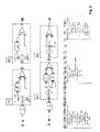
So far, correspondences have been used to identify elements that have been added or removed from a process model. However, there are also other changes that can occur. For example, elements of a process model can be reordered, causing changes to the control or data flow (referred to collectively herein as control flow changes) of a model. Control flow changes are more difficult to detect and also have an influence on addition and removal of elements. Further, existing techniques lack the sophistication required to handle addition and deletion of control action node elements, such as decision, merge, fork and join elements. If addition of such elements is done in isolation then an invalid model can easily be created.
SUMMARY OF THE INVENTION
One aspect of the present invention provides a method for production in a data processing system of a difference log defining differences between process models defined in memory of the system. The method comprises:
for each of the process models, providing in the memory model structure data defining a hierarchy of SESE regions representing the structure of that model;
providing in the memory model comparison data defining correspondences between elements of the models;
providing in the memory region comparison data defining correspondences between regions of the SESE region hierarchies for the models;
analyzing the model comparison data and the region comparison data to identify differences between the SESE region hierarchies; and
producing a difference log defining said differences in the memory, the difference log indicating, for each difference, a region of at least one of said SESE region hierarchies in which that difference occurs.
Thus, in embodiments of the present invention, a difference log defining differences between process models can be produced automatically based on representations of the process model structure as a hierarchy of SESE regions. In particular, in addition to model comparison data which defines correspondences between elements of the models, region comparison data is provided. This defines correspondences between regions of the SESE region hierarchies for the models. By analyzing both the model comparison data and the region comparison data, differences between the SESE region hierarchies can be identified. Based on this analysis, a difference log can be generated in which differences are associated with regions of a SESE region hierarchy in which they occur. This greatly facilitates identification and appropriate handling of the differences that need to be resolved in model merging processes. For each region, any differences occurring in that region can be identified from the difference log and differences can be addressed on a region by region basis throughout the SESE region hierarchy. Different categories of differences can be identified, for instance control flow differences can be identified as well as mere addition or deletion of model elements, and dependencies between differences that are important in process merging can be detected and dealt with accordingly. Moreover, this technique provides a basis for systematic resolution of differences which does not rely on the prior existence of a change log. Rather, the difference log corresponds in effect to one possible change log, and one which, by linking differences to the process model structure via the SESE regions, provides the basis for efficient and comprehensive difference resolution in process merging operations.
In general, for any given difference defined in the difference log, the log could indicate, directly or indirectly, one or more regions of one or more of the SESE region hierarchies to which that difference relates. However, in preferred embodiments, the difference log defines a hierarchy of regions corresponding to a combined SESE region hierarchy which combines the SESE region hierarchies for the models and is defined by combined hierarchy data in the memory. Each difference is then indicated in the region of the difference log hierarchy corresponding to the region of the combined SESE region hierarchy in which that difference occurs. Here, the region of a given SESE region hierarchy in which a difference occurs can be indicated simply by inclusion of that difference in the region of the difference log hierarchy corresponding to the appropriate combined hierarchy region. Thus, a structured difference log is produced, the difference log having a hierarchical structure corresponding to the structure of the process models. This provides an efficient difference representation which can be displayed to a user for convenient, user-friendly visualization and resolution of differences as discussed further below.
Methods embodying the invention preferably include, in response to user input indicating a region of a said SESE region hierarchy, identifying from the difference log any differences associated with that region, and producing a difference display displaying those differences to the user. In general, associated differences here could be those indicated by the log as occurring in the user-specified region and/or those occurring in the corresponding region(s) of the or each other SESE region hierarchy. However, in the preferred case just described where the difference log has a hierarchical structure, in response to a user input indicating a region of a SESE region hierarchy, any differences indicated in the corresponding region of the difference hierarchy can be identified and displayed in the difference display. To further facilitate assessment and handling of differences, the difference display preferably includes a representation of the user-specified SESE region plus a representation of any corresponding region(s) of the or each other SESE region hierarchy.
Embodiments can be envisaged in which the combined hierarchy data has been previously generated and stored in memory for the process models in question. However, the process of difference log production may include processing the region comparison data and the model structure data for the models to generate the combined hierarchy data. Similarly, the region comparison data for the process models may have been previously generated and stored in memory in some embodiments. In other embodiments, the difference log production process may include the steps of comparing regions of the SESE region hierarchies defined by the model structure data to detect the correspondences between regions, and generating the region comparison data defining those correspondences. Embodiments can also be envisaged in which the model structure data defining the SESE region hierarchies has been previously generated for the models. For example, more sophisticated metamodels might be available in future whereby SESE regions are inherent in the basic definition of a model. Thus, the model structure data which defines the SESE region hierarchy could be the fundamental model definition in the system. However, allowing for less sophisticated model definitions, the difference log production process may include the steps of analyzing a model defined in system memory to detect hierarchical SESE regions thereof, and generating the model structure data defining the SESE region hierarchy for that model. This may be done for one or more of the models as required.
Where the region comparison data is generated automatically in the difference log production, the model comparison data be updated after generation of the region comparison data to include any new correspondences between elements of corresponding regions of the two models. This will be discussed further below. Similarly, in response to user input modifying a process model to eliminate a difference, the model structure data for that model can be updated accordingly and the difference log updated to eliminate that difference. The update process here can involve updating correspondences between model elements and/or SESE regions as required.
Preferred embodiments include various additional features to facilitate merging operations. For example, embodiments can suggest insertion points in a SESE region hierarchy for hierarchy elements which need to be moved or inserted to resolve a difference between the models. Embodiments can also filter identified differences, such as differences relating to control action node elements, to eliminate differences which are not of interest to the merging operation. These techniques will be discussed further below.
A second aspect of the invention provides a computer program comprising program code means for causing a data processing system to perform a method according to the first aspect of the invention. It will be understood that “data processing system” is used here in the most general sense and includes any device, component or distributed system which has a data processing capability for implementing a computer program. Such a computer program may thus comprise separate program modules for controlling different components of a distributed system where provided. Moreover, a computer program embodying the invention may constitute an independent program or may be a component of a larger program, and may be supplied, for example, embodied in a computer-readable medium such as a disk or an electronic transmission for loading in a computer system. The program code means of the computer program may comprise any expression, in any language, code or notation, of a set of instructions intended to cause data processing system to perform the method in question, either directly or after either or both of (a) conversion to another language, code or notation, and (b) reproduction in a different material form.
A third aspect of the invention provides a system for producing a difference log defining differences between process models. The system comprises:
memory for storing, for each of the process models, model structure data defining a hierarchy of SESE regions representing the structure of that model, model comparison data defining correspondences between elements of the models, and region comparison data defining correspondences between regions of the SESE region hierarchies for the models; and
control logic adapted to analyze the model comparison data and the region comparison data to identify differences between the SESE region hierarchies, and to produce and store in the memory a difference log defining said differences, the difference log indicating, for each difference, a region of at least one of said SESE region hierarchies in which that difference occurs.
In general, where features are described herein with reference to an embodiment of one aspect of the invention, corresponding features may be provided in embodiments of another aspect of the invention.
BRIEF DESCRIPTION OF THE DRAWINGS
Preferred embodiments of the invention will now be described, by way of example, with reference to the accompanying drawings in which:
FIG. 1 is a schematic representation of a modeling system incorporating a difference log production system embodying the invention;
FIG. 2 is a flow chart illustrating key steps in operation of the difference log production system;
FIG. 3 illustrates decomposition of a process model into SESE regions;
FIG. 4 illustrates a process structure tree representing the hierarchy of SESE regions in FIG. 3;
FIG. 5 shows SESE regions of two models illustrating region matching considerations;
FIG. 6 shows a difference display produced by the FIG. 1 system illustrating an inter-region control flow difference;
FIG. 7 shows another difference display illustrating a complex control flow difference;
FIG. 8 shows a further difference display illustrating a control flow difference within a sequential SESE region;
FIG. 9 shows an example of corresponding SESE regions used in explaining an insertion point identification technique employed in the FIG. 1 system;
FIGS. 10 and 11 show examples of corresponding SESE regions using in explaining a difference filtering technique employed in the FIG. 1 system; and
FIG. 12 illustrates corresponding SESE regions in a scenario where adjustment of correspondences is performed in the FIG. 1 system.
DETAILED DESCRIPTION OF THE INVENTION
The present invention makes use of a technique not previously applied in the field of process model merging as a basis for addressing various issues with prior techniques discussed above. This technique involves Single-Entry-Single-Exit (SESE) regions. SESE regions originated in work on compiler theory and are discussed in: “The Program Structure Tree: Computing control regions in linear time”, R. Johnson, D. Pearson, and K. Pingali, Proceedings of the ACM SIGPLAN'94 Conference on Programming Language Design and Implementation, pages 171-185, June 1994; and “Faster and More Focused Control-Flow Analysis for Business Process Models through SESE Decomposition”, J. Vanhatalo, H. V?lzer, and F. Leymann, LNCS 4749, pp. 43-45, Springer September 2007. Briefly, a SESE region is a defined subset of the set of elements and their interconnecting edges which make up the structure of a model as will be explained in more detail below.
FIG. 1 is a schematic representation of a modeling system, indicated generally at 1, showing the main components involved in the difference log production process. In this embodiment the system 1 is implemented by specialized software running on a general-purpose computer with the usual user interfaces for input and display. The main components of system 1 are represented generally in the figure by memory 2 and a difference log generator 3. The difference log generator 3 includes components indicated as a model analyzer 4, a region matcher 5 and a difference analyzer 6. The system memory 2 stores various information for operation of the system, including process models A and B, defined by respective software modules, and model comparison data “CompM” for the two models as described below. The memory 2 also holds various other data generated in operation of the system. This comprises model structure data, defining a hierarchy of SESE regions for each of models A and B, region comparison data “CompR” described further below, and the difference log itself which is based on a combined SESE region hierarchy for the models as described below. The difference log generator 3 comprises control logic for implementing the difference log production process described below. In general, this control logic could be implemented in hardware, software or a combination thereof. In this embodiment, however, the difference log generator logic is implemented by software running on computer system 1, with respective software modules providing the model analyzer 4, region matcher 5 and difference analyzer 6. Suitable software will be apparent to those skilled in the art from the description of operation herein.
The difference log production is described below in relation to merging of two process models A and B. The model merging process utilizes model comparison data in the form of comparison file CompM which defines correspondences between elements of the two models. Various systems are known for defining correspondences between model elements, for example as described in the documents referenced earlier. The preferred embodiment described here employs the correspondence system disclosed in the Küster et al. references above. Briefly, using this system the comparison CompM can include different types of correspondences such as a 1-1 correspondence, a 1-0 correspondence and a 0-1 correspondence described earlier. Further correspondences include the 1-many (1-m) correspondence and the many-1 (m-1) correspondence which specify that a single element of one model corresponds to a number of elements in the other model. By analyzing the correspondences between elements of models A and B in accordance with this system, the comparison CompM can be derived as a correspondences file for the models specifying the identities of corresponding elements in the two models. The particular way in which this comparison is derived is not central to the present invention and need not be described here. It suffices that such a comparison defining correspondences between the model elements is provide in memory 2 for use in generation of the difference log.
The flow chart of FIG. 2 provides an overview of system operation, indicating the main steps of a model merging process involving generation of a difference log. Step 10 of this figure represents generation of the model structure data defining the SESE region hierarchies for models A and B. This step is performed by model analyzer 4 of difference log generator 3 based on analysis of the model definitions in memory 2. The process of generating the SESE region hierarchies is described in more detail below with reference to FIGS. 3 and 4. Step 11 of FIG. 2 represents generation of the region comparison data CompR. This step is performed by region matcher 5 of difference log generator 3 and essentially involves comparing regions of the SESE region hierarchies to identify corresponding, or “matching”, regions in the two hierarchies. The result of this process is a region comparison file CompR, similar to the model comparison file CompM, but defining the identified correspondences between regions of the two SESE region hierarchies. The region matching process will be discussed in more detail below.
Step 12 of FIG. 2 represents the core of the difference log generation process. This is performed by the difference analyzer 6 of difference log generator 3 and involves analysis of the model comparison file CompM and the region comparison file CompR to identify differences between the SESE region hierarchies for the models. This step involves identification of various different categories of differences as discussed in more detail below. The identified differences are stored in the form of a hierarchical difference log structure in system memory 2. The hierarchical structure of the difference log reflects the hierarchical structure of the process models. In particular, the difference log structure is based on a combined SESE region hierarchy which combines the SESE region hierarchies for the two models. Generation of the combined hierarchy will be described further below. In the hierarchical difference log, differences are associated with the regions of the model region hierarchies in which they occur by indicating each difference in the appropriate region of the combined hierarchy structure. In this preferred embodiment, the difference log also records, for each region of the difference hierarchy, the basic structure of the corresponding region(s) of the two model region hierarchies. This provides the basis for an exceptionally user-friendly difference display as demonstrated below. Where appropriate, differences are recorded in the difference log by difference analyzer 6 in the form of an instruction or operation to be performed to resolve that difference. For example: a difference concerning a missing element x might be expressed as “add element x”; a difference relating to reordering of elements might be expressed as “move element y”, and so on. Difference analyzer 6 also performs various subsidiary tasks such as identification of possible insertion points for elements to be added or moved, and filtering of identified differences relating to control action nodes. These tasks will be discussed further below.
After generation of the difference log, differences can be displayed to a user who can interact with the system to modify the models to eliminate differences. This process is represented by step 13 of FIG. 2. The user can call up a difference display displaying the contents of the difference log corresponding to any region of the SESE region hierarchies. In particular, in this embodiment, a user can input any region of either hierarchy, and the system will display the contents of the corresponding region of the difference log hierarchy. The difference display also includes a representation of the corresponding regions of the two model hierarchies. The user can thus navigate through the hierarchical model structure, viewing the corresponding regions of the difference log, and can equally navigate through the difference log hierarchy viewing the relevant structure of the two process models. The difference display produced by difference log generator 3 will be illustrated by examples below. When viewing differences, the user can modify either model as required to eliminate differences. The user can, for example, select a hierarchy region and resolve all differences within that region. In any case, in response to user input changing a model, the model analyzer 4 can update the SESE region hierarchy representation accordingly, and the difference analyzer 6 can update the difference log to reflect the change. Where appropriate depending on the nature of the modification, the difference analyzer 6 will also update the correspondence files CompM and CompR to reflect any altered correspondences.
The process of generating the SESE region hierarchies in step 10 of FIG. 2 will now be explained in more detail. In order to associate differences between process models with the areas in which they occur, the structure of each process model is computed by model analyzer 4 using the concept of SESE regions as illustrated in FIG. 3. This figure shows a simple process model and its decomposition into SESE regions. A SESE region is depicted as a dotted box. Let G=(N, E) be a process model, where N is the set of nodes in the process model and E is the set of edges in the process model. A SESE (single-entry-single-exit) region (“region” for short) R=(N′, E′) is a nonempty subgraph of G, i.e., N′
Figure US08572551-20131029-P00001
N and E″=E∩(N′×N′) such that there exist edges e, e′εE with E∩((N\N′)×N′)={e} and E∩(N′×(N\N′))={e′}; e and e′ are called the entry and the exit edge of R respectively.
The process model in FIG. 3 has more regions than those that are shown explicitly. For example, the union of the regions J and K, denoted J∪K, as well as K∪L are also regions. These, however, are not interesting to us and they are subsumed in region X. Interesting regions will be called “canonical” as defined in the following. We say that two regions R and R′ are in sequence if the exit edge of R is the entry edge of R′ or vice versa. The union R∪R′ of two regions R and R′ that are in sequence is a region again. A region R is non-canonical, if there are regions X, Y, Z such that X and Y are in sequence, R=X∪Y, and R and Z are in sequence, otherwise R is said to be canonical. The regions shown in FIG. 3 are exactly the canonical regions of that process model. Since canonical regions are the most interesting for our purposes, only canonical regions are considered in the preferred system of FIG. 1. In the following description of operation, therefore, we will mean ‘canonical region’ whenever we say ‘region’.
For each process model A and B in memory 2, model analyzer 4 calculates the SESE regions as defined above using known techniques of compiler theory as detailed in the references given earlier. Since canonical regions do not overlap but are either nested or disjoint, it is possible to organize the canonical regions in a unique tree. We call this tree the “process structure tree” of a process model. This process structure tree is computed by model analyzer 4 in this embodiment as a convenient representation of the SESE region hierarchy of a model. The process structure tree can be computed in time linear in the size of the process model. FIG. 4 shows the process structure tree representing the region hierarchy of the process model from FIG. 3. A region is represented as a boxed tree node. In addition, the nodes of the process model are represented for convenience as leaves in the tree. The parent of a region R (being a process model node n) is the smallest region R′ that contains R (node n). We then also say that R is a child region of R′ (n is a child node of R′).
Thus, on completion of step 10 of FIG. 2, the process structure trees representing the SESE region hierarchies for models A and B are stored in memory 2. Region matcher 5 then analyzes these hierarchies, performing a region matching process to identify corresponding (matched) regions in the two hierarchies. Basically this process involves comparing regions of the two hierarchies and applying some predefined matching strategy to determine whether regions are matching or not. Various matching strategies could be employed as desired here, but in the following we describe an exemplary matching strategy which can be applied by region matcher 5.
FIG. 5 illustrates the SESE region matching problem. It shows four SESE regions that have been identified in two process models A and B. However, identifying the SESE regions in both process models does not automatically establish a connection between regions in the two models. As a first strategy for matching, one could consider two regions to be matched if they contain corresponding entry and exit elements. For example, in FIG. 5, this strategy would indicate a match if the control action nodes (i.e. decision, merge) have 1-to-1 correspondences in the file CompM and have not been deleted and recreated. However, if the latter condition is not satisfied, the strategy will not lead to a matching. In such a case, one might consider a matching based on the enclosed elements. We first describe a number of different strategies for matching and then explain a comprehensive strategy adopted in this embodiment:
Strategy S1: Given a region R1 and a region R2, they are considered to be matching if they have corresponding entry and exit nodes.
Strategy S2: Given a region R1 and a region R2, they are considered to be matching if they have a corresponding entry or exit node.
Strategy S3: Given a region R1 and a region R2, they are considered to be matching if they have corresponding elements inside.
Strategy S4: Given a region R1 and a region R2, they are considered to be matching if they contain regions R3 and R4 which are matching.
A combination of individual strategies is required as only one strategy will lead to bad results. For example, strategy S1 individually will lead to lots of unmatched regions if control nodes are deleted and recreated. The comprehensive strategy employed by region matcher 5 in this embodiment involves the following steps:
1. Given a set of regions R, we compute a matching according to S4. If we get more than one candidate, we apply strategy S3. We remove all matched regions from the set of regions R.
2. Given a set of regions R, we compute a matching according to S3. If we get more than one candidate, we apply strategy S1 and S2. We remove all matched regions from the set of regions R.
3. Given a set of regions R, we compute a matching according to S2. We remove all matched regions from the set of regions R.
4. Given a set of regions R, we compute a matching according to S1. We remove all matched regions from the set of regions R.
This strategy first searches for matching regions based on already matched regions within the candidates and based on matching elements inside the regions. Suitable algorithms for implementing this strategy in region matcher 5 will be apparent to those skilled in the art. The result of the region matching process is the region correspondences file CompR defining the matched regions of the two SESE region hierarchies. After this process, region matcher 5 may update the model element correspondences file CompM to include any new correspondences resulting from matching of SESE regions. This will be described further below.
As indicated above, the core difference log generation process is performed by difference analyzer 6 in step 12 of FIG. 2. This involves computing a combined SESE region hierarchy for the models and identifying and recording differences associated with the various regions of this hierarchy. In particular, difference analyzer 6 processes the individual region hierarchies for models A and B in conjunction with the region correspondences file CompR to generate combined hierarchy data defining this combined SESE region hierarchy. The combined hierarchy is represented in the form of a combined SESE tree which is generated from the individual process structure trees for models A and B in accordance with the following process.
Given two process structure trees SESETREE(V1), SESETREE(V2) and correspondences between their nodes defined by the correspondence file CompR, then the combined SESE tree is denoted by SESETREE(V1, V2). We also assume a function father: V→V which maps a node νεV to its father in the SESE tree. The combined SESE tree can be constructed as follows:
    • for a node ν1εSESETREE(V1) that has a corresponding node ν2εSESETREE(V2), a node ν3 is inserted into SESETREE(V1, V2) with father(ν3)=father(ν2);
    • for a node ν1εSESETREE(V1) that does not have a corresponding node, a node ν3 is inserted into SESETREE(V1, V2) with father(ν3)=father(ν1);
    • for a node ν2εSESETREE(V2) that does not have a corresponding node, a node ν3 is inserted into SESETREE(V1, V2) with father(ν3)=father(ν2).
      The Following pseudo Code Indicates this Process:
百度 良渚王朝有一个王城,那就是良渚古城遗址。
// createJointSESETree( ) is invoked with the root region of the
primary model
// createJointSESETree( primaryModel.getRootRegion( ) )
create JointSESETree( Region region ) {
// create node that represents the given region in the tree
node = new Node( region )
// add all subregions of the given region to the tree
foreach subRegion of region {
node.addChildren( create JointSESETree( subRegion ) )
}
// add all subregions of secondary model that have no
corresponding subregion in the primary model
if (region is in the primary model) {
foreach subRegionB of region.getCorrespondingRegion( ) {
if (subRegionB.getCorrespondingRegion( ) == null) {
// subRegionB has no counterpart in the primary model
node.addChildren( create JointSESETree(
subRegionB ) )
}
}
}
}
Having computed the combined SESE tree for the models, difference analyzer 6 can generate the hierarchical difference log by identifying and recording differences occurring in the various regions of the combined SESE hierarchy. That is, a difference occurring in a region of one of the two model region hierarchies, say the model A hierarchy, is recorded in the difference log for the region of the combined SESE region hierarchy which corresponds to that model A region. In this embodiment, this is performed by enriching the nodes of the combined SESE structure tree with the identified differences. This is done as follows for differences expressed by operational instructions “Move”, “Delete” and “Insert” as discussed further below:
if difference=Insert then difference is associated with the node representing the region in which difference takes place;
if difference=Delete then difference is associated with the node representing the region in which difference takes place;
if difference=Move then difference is associated with the node representing the region into which the element is moved and the node representing the region out of which the element is moved;
if difference=InsertRegion or difference=DeleteRegion, then difference is associated with the node in SESETREE(V1, V2) representing this region.
The resulting difference log represents, in effect, one possible change log for the two process models. Differences are identified by analyzing the model and region correspondences files CompM and CompR for various different categories of differences. The difference analyzer can distinguish between the following types of differences that can occur:
Category 0—differences between two corresponding model elements
Category 1—differences between the sets of elements (excluding edges)
Category 2—simple control flow differences
Category 3—complex control flow differences.
A difference between two corresponding model elements (Category 0) occurs if attributes of a task or subprocess have been changed. Category 1 differences occur if model elements such as tasks or subprocesses are deleted or added to one of the models. Category 2 differences deal with the situation that tasks or subprocesses have been reordered. Category 3 differences occur if parallel or alternative regions are added or deleted.
Difference analyzer 6 calculates Category 0 differences by comparing corresponding elements and then comparing each of the attributes. Category 1 differences can be easily calculated: each 0-1 correspondence and 1-0 correspondence gives rise to such a difference. Category 2 differences are calculated using two approaches: for control-flow changes within a SESE region, difference analyzer 6 uses a method described below. Control-flow changes across SESE regions can be detected by comparing elements of each SESE region that do not have 0-1 or 1-0 correspondences. Category 3 differences are calculated simply by identifying newly inserted and deleted SESE regions. In the following, we elaborate on the calculation and visualization of Category 2 differences and Category 3 differences.
Category 2 differences can occur due to two changes: elements may have been moved from one region to another, and elements may have been moved within a region. The former changes can be easily identified as follows. For each element in the primary model, e.g. model B, the corresponding element in the secondary model, model A, is identified from the CompM file. For each element, the SESE region directly enclosing that element is identified from the corresponding region hierarchy. Difference analyzer 6 then determines from the CompR file whether the two regions have been matched. If yes, the element in the secondary model A has not been moved to another region compared to primary model B, otherwise it has been moved. The following algorithm gives an implementation of this process.
For all Elements e in the Primary Model
{
secondaryelement = getCorrespondingElement(e);
Region rprimary = e.getParentRegion( );
Region rsecondary = secondaryelement.getParentRegion( );
If (!rprimary.getMatchingRegion( ) == rsecondary)
{
AbstractDifference = new MoveDifference(secondaryelement);
}
}
FIG. 6 shows an example of the difference display displayed to a user for an inter-region control flow difference recorded in the difference log. In the secondary model A in this figure, the task Task:3 has been moved from R2′ to R1′. This is identified using the previous algorithm and visualized in the difference view as shown. The upper section of the difference view displays a representation of the corresponding regions of the two models in which the difference occurs. The lower section of the display displays the contents of the region of the hierarchical difference log structure corresponding to the relevant regions of the two models. In particular, the central column gives details of the difference based on the structure of the combined region hierarchy described above. This indicates the difference in question in the form of an operational instruction “Move Task 3”. The left and right hand columns give details of the structure of the corresponding regions of the models B and A respectively. Although not indicated in this particular view, difference analyzer 6 can also calculate and display an appropriate insertion point in the model structure for the element to be moved. This is done using a “fixpoint” technique which will be described later.
Complex control flow differences arise if SESE regions are newly inserted or deleted. Newly inserted SESE regions can be identified because for those no matching partner in the primary model will be found, deleted SESE regions can be identified because for those no matching partner in the secondary model can be found. The following pseudo code provides an implementation for calculating those complex control flow differences in difference analyzer 6.
Calculation of Deleted Regions:
List deletedRegions = new ArrayList( );
Iterator subRegions = PrimaryModel.getRegionsOfGraph( ).iterator( );
while (subRegions.hasNext( )) {
Region subRegion = (Region) subRegions.next( );
if (subRegion.getMatchingRegion( )==null) {
deletedRegions.add(subRegion);
}
}

Calculation of Inserted Regions:
List insertedRegions = new ArrayList( );
Iterator subRegions = SecondaryModel.getRegionsOfGraph( ).iterator( );
while (subRegions.hasNext( )) {
Region subRegion = (Region) subRegions.next( );
if (subRegion.getMatchingRegion( )==null) {
insertedRegions.add(subRegion);
}
}

FIG. 7 shows an example of the difference display where a complex control flow difference occurs. In the secondary model A a new region (an Alternative Region) has been added. This is identified using the previous algorithm and visualized in the difference view. Again, difference analyzer 6 can calculate an insertion point for this alternative region using the fixpoint technique described below.
An example of a control flow difference occurring in a linear sequential SESE region is illustrated in the difference view of FIG. 8. Such differences can be identified by difference analyzer 6 in various ways based on analysis of predecessor and successor elements of a given element in the control flow. For example, given an element n in the primary model, its control flow conflicts are calculated as follows. First, its predecessors and successors in the primary model are calculated. Second, the predecessors and successors of the corresponding element n′ in the secondary model are calculated. Third, these sets are compared. If a node x is a predecessor in the primary model but a successor in the secondary model, this represents a control flow conflict. If a node x is a successor in the primary model but a predecessor in the secondary model, this represents a control flow conflict as well. Based on the identified conflicts as will be apparent to those skilled in the art, difference analyzer 6 can detect changes to the control flow and express these as a set of operations to resolve the control flow conflicts. This is indicated in the difference view of FIG. 8 for the particular control flow difference illustrated.
The fixpoint technique mentioned above will now be described in more detail. In the case of differences identified as move operations in the difference log, the user should be told where the element can be moved to in order to resolve the difference. In case of differences identified as insertion operations, the user should be told where the element can be inserted. For this purpose, we introduce the concept of fixpoints. Fixpoints are used to determine the edges of a region in the primary process model, where an element has to be inserted or moved to, according to its position in the matching region in the secondary process model. A formal definition of fixpoints is given first:
An element xP of the primary process model is called fixpoint, if it has a corresponding element xS in the secondary process model and the following requirements are fulfilled:
    • the surrounding regions of xP and xS are matching,
    • xP has not been marked as moved.
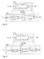
      FIG. 9 provides an example and depicts two process models. The upper one is a primary process model P and the lower one a secondary process model S.
      Between P and S in FIG. 1 the following differences will be detected by the difference analyzer 6:
    • Move element B (Move element A instead of B would also be possible, though in the following we assume Move element B)
    • Insert X
    • Delete D
      All differences concern the matching regions RP and RS delimited by the outer rectangles. According to our definition of Fixpoints the elements Start, B, C and Stop are Fixpoints of region RP of the primary process model. In FIG. 9 the Fixpoints of RP and their corresponding Fixpoints RS are highlighted with dashed rectangles.
For each detected Move and Insert difference the calculation of Fixpoints is divided into two steps: the calculation of a Fixpoint predecessor and the calculation of a Fixpoint successor. In order to calculate the Fixpoint predecessor of the Insert X difference, the algorithm starts at the position of X in the secondary process model and examines the predecessors of X in reverse control flow order. The first predecessor is element A, which fulfills all requirements of our definition of a Fixpoint, thus A is the Fixpoint predecessor of X. The calculation of the Fixpoint successor of X is analogous to the calculation of the Fixpoint predecessor, except that the successors of X are examined in control flow order. The Fixpoint successor of X is C. So X has to be inserted in the primary process model between A and C, in other words the edges (A-B) and (B-C) are possible insertion points. The following algorithms calculate the Fixpoint predecessor and successor for a given element e.
getFixpointPredecessor(e) {
for each e.getPredecessors p {
if (p.hasCounterpartInParentRegion( ) &&
!p.isMovedWithinRegion( )) {
return predecessor;
} else {
return getFixpointPredecessor(p);
}
}
return null;
}
getFixpointSuccessor(e) {
for each e.getSuccessors s {
if (s.hasCounterpartInParentRegion( ) &&
!s.isMovedWithinRegion( )) {
return predecessor;
} else {
return getFixpointSuccessors(s);
}
}
return null;
}

Thus, the SESE region hierarchies for the models can be analyzed (together with the models themselves if necessary for any control flow information not directly indicated in the hierarchies) to identify insertion points for elements. When an insertion point has been calculated by difference analyzer 6, this can be recorded in the difference log and displayed to the user as required.
The foregoing describes the detection and visualization of elements if they are moved, inserted or deleted. However, there are elements that should be treated in a different way. In particular, if a control action node element (such as a decision, merge, fork or join node) is moved from one SESE region to another, it does not always make sense to visualize it as a moved element. FIG. 10 shows such an example. In this example, we assume that there is a 1-to-1 correspondence between the first decisions and last merges in models B and A, as indicated by the bold dashed lines. The other merge and Decision represent newly inserted elements in process model A. We further assume that R1 and R2 are matched and that R3 represents a newly inserted region. Note that in such a case it does not make sense to visualize the last merge as a moved element and the first merge and Decision:2 as newly inserted elements in region R2 and region R3, respectively, because they are both part of a well-formed SESE region and they represent the entry and exit elements of these regions. If they were visualized and offered for addition or offered to be moved, then this would lead to an incorrect process model.
On the other hand, there are cases where such control actions should be visualized as newly inserted elements or moved elements. This is the case if they are not entry or exit elements of a well-formed SESE region, such as in FIG. 11. Here, the Decision:3 has been newly inserted and it should be visualized as such an element. All the other elements should not be visualized as moved or newly inserted because they are first or last elements of SESE regions. In a similar way, we can treat deleted control actions which are then created again, and which will lead to 1-to-0 and 0-to-1 correspondences in the comparison. If no additional actions are taken, they will be represented as deleted and inserted elements. As a consequence, we describe below an approach whereby difference analyzer 6 can distinguish between those elements that should be visualized and those that should not. In accordance with this technique, the decision whether to include a difference relating to a control action node in the difference log is dependent on whether that control action node and any corresponding element in the other SESE region hierarchy are boundary node elements, where a “boundary node element” here is an entry or exit node of a SESE region.
The difference analyzer applies the following basic rules for inclusion of control action changes in the difference log, and hence visualization of these changes in the difference display.
(R1) If the control action is an entry/exit of a region in the primary model and is not an entry/exit of a region in the secondary model, this change will be visualized.
(R2) If the control action is an entry/exit of a region in the primary model and remains an entry/exit of a region in the secondary model, this change will not be visualized.
(R3) If the control action is not an entry/exit of a region in the primary model and becomes an entry/exit of a region in the secondary, this change will be visualized.
Additional rules can be constructed for dealing with the case where the control action is not an entry/exit of region in the primary model and remains such a node, allowing this change to be visualized in some cases and not in others. Possible rules here will be apparent to those skilled in the art. In simple embodiments, however, the difference analyzer may simply include such differences for visualization in the difference display.
The above explains how and why control action elements should be treated in a special way for change visualization. For a two-way merge of two process models, this is sufficient. However, there are scenarios where correspondences should be adjusted after region matching if control action changes have been made. This is explained in the following.
Overall, region matching is used to identify similar regions. This region matching is partially based on corresponding entry/exit nodes of two regions. We have explained that this strategy is not sufficient if control actions are deleted and recreated or if they are moved to other regions. In such cases, the result of region matching contains additional information that is not present in the correspondences. After process model merging, this additional information is lost if it is not encoded into correspondences. As a consequence, in merging scenarios where this additional information is important, correspondences should be adapted after region matching. Such a scenario is illustrated in FIG. 12. Here, we assume that models V1 and V2 are derived independently from a model M. We further assume that during such derivations, the control action nodes in regions R3 and R4 are deleted and newly created. Nevertheless, using the region matching approach described above, R2 will be matched with R3 and R4 when comparing M and V1 and M and V2. We can also compare V1 and V2 directly as has been described in “Methodology and Tooling for Business Processes with Automated Correspondence Calculation”, Küster et al., IP.com, IPCOM000151093D, April 2007. However, as no correspondences exist between the control action nodes in R2 and R3 as well as R2 and R4, the transitive correspondences between these control action nodes will not be established (see the reference just mentioned for a detailed algorithm defining how this can be done). Further, our region matching will not be able to match region R3 and R4 because they also do not contain any corresponding elements, as these have been deleted. As a consequence, a deleted and a newly inserted region will be displayed, which is not very useful. However, if the correspondences between M and V1 and M and V2 are adjusted after region matching has taken place, the region matching information will be encoded into the correspondences. For example, if region R2 in M is matched with region R3 in V1, one could re-establish 1-to-1 correspondences for the entry/exit control actions. If this is done also for region R4 in V2 and region R2 in M, then the transitive correspondences between the entry/exit nodes in R3 and R4 will exist and then the comparison between V1 and V2 will show that Task:5 is deleted and Task:6 is inserted. This example shows the necessity of adjusting correspondences if the models are used in further comparisons. The algorithm below indicates an approach which can be employed by region matcher 4 to achieve this.
For all regions R in the primary model do
{
if r has a matching region Rm in the secondary model
{
adjustCorrespondencesofEntryAndExitNodes(R,Rm);
}
}
procedure adjustCorrespondencesofEntryAndExitNodes(R,Rm)
{
if entrynode(R) has no correspondence to entrynode(Rm)
{
removeCorrespondence(entrynode(R));
removeCorrespondence(entrynode(Rm));
insertCorrespondence(entrynode(R),entrynode(Rm);
}
if exitnode(R) has no correspondence to entrynode(Rm)
{
removeCorrespondence(exitnode(R));
removeCorrespondence(exitnode(Rm));
insertCorrespondence(exitnode(R),exitnode(Rm);
}
}
As described earlier, the user can navigate through the difference log, viewing the difference display, and interact with the system to eliminate differences between the models. In response to user input changing a model, the model analyzer 4 can update the SESE region hierarchy representation, and the difference analyzer 6 can update the difference log to reflect the change. Difference analyzer 6 can also update the correspondence files CompM and CompR as necessary to reflect any altered correspondences resulting from merging operations. The difference display generated from the structured difference log presents differences in a way that is particularly useful for the modeler, facilitating handling of large numbers of changes to large process models. When given a large process model, a long list of differences would be confusing. However, system 1 displays differences in a structured way that is similar to the structure of the process model itself. This enables the detection of dependent changes such as the insertion of a decision and a merge node with additional tasks in between. (See, for example, FIG. 7 where the dependency between the addition of region R2′, as a first difference, and the addition of the elements within that region as subsidiary differences, must be respected. That is, the first difference must be resolved before the subsidiary differences are dealt with.) The system also allows treatment of other dependent changes in a suitable way, e.g. to forbid the insertion of a decision node without the insertion of the following merge node. The association of differences with the SESE regions they occur in also allows distinguishing of different categories of differences and the handling of these different categories in a systematic way. System 1 also facilitates a layered approach to resolving differences, whereby structural differences can be resolved first, then attribute differences can be dealt with. For this purpose, a new attribute difference display could be generated that focuses on displaying attribute differences for elements that have a 1-to-1 correspondence. Overall, therefore, it will be seen that system 1 provides a highly efficient tool for comprehensive difference resolution in process merging operations, and one which does not rely on the prior existence of a change log.
It will of course be appreciated that many changes and modifications can be made to the particular embodiments described above without departing from the scope of the invention. For example, while the operation of the above embodiment has been described in connection with merging of two process models, the same principles can be applied in general to merging of two or more process models.

Claims (20)

The invention claimed is:
1. A method for production in a data processing system of a difference log defining differences between a plurality of process models defined in memory of the system, the method comprising:
for each process model of the plurality of process models, providing, in a memory, model structure data defining a hierarchy of Single-Entry-Single-Exit (SESE) regions representing the structure of that process model;
providing, in the memory, model comparison data defining correspondences between elements of the process models;
comparing regions of the SESE region hierarchies defined by said model structure data to detect correspondences between regions and to generate region comparison data defining the correspondences and providing, in the memory, region comparison data defining correspondences between regions of SESE region hierarchies for the process models;
analyzing the model comparison data and the region comparison data to identify differences between the SESE region hierarchies; and
producing a difference log defining said differences in the memory, the difference log indicating, for each difference, a region of at least one of said SESE region hierarchies in which that difference occurs.
2. A method according to claim 1 including providing, in the memory, combined hierarchy data defining a combined SESE region hierarchy comprising the SESE region hierarchies for the process models, wherein the difference log has a hierarchy of regions corresponding to the combined SESE region hierarchy, each difference being indicated in the region of the difference log hierarchy corresponding to the region of the combined SESE region hierarchy in which that difference occurs.
3. A method according to claim 2 including processing the region comparison data and the model structure data for the process models to generate said combined hierarchy data.
4. A method according to claim 1 further comprising displaying at least one of a difference, regions including differences, and operational instructions for modifying at least one process model to address at least one difference.
5. A method according to claim 1, further comprising step of:
receiving at least one update to at least one process model;
generating new region comparison data; and
after generating said new region comparison data, updating said model comparison data to include any new correspondences between elements of corresponding regions of the process models.
6. A method according to claim 1 including analyzing at least one of the process models defined in system memory to detect hierarchical SESE regions thereof, and generating the model structure data defining the SESE region hierarchy for that process model.
7. A method according to claim 1 including, in response to user input indicating a region of said SESE region hierarchy, identifying from the difference log any differences associated with that region, and producing a difference display displaying said differences to the user.
8. A method according to claim 7 including providing, in the memory, combined hierarchy data defining a combined SESE region hierarchy comprising the SESE region hierarchies for the process models, wherein the difference log has a hierarchy of regions corresponding to the combined SESE region hierarchy, each difference being indicated in the region of the difference log hierarchy corresponding to the region of the combined SESE region hierarchy in which that difference occurs, and wherein, in response to said user input indicating a region of a SESE region hierarchy, any differences indicated in a corresponding region of the difference hierarchy are identified and displayed in said difference display.
9. A method according to claim 7 wherein said difference display displays a representation of the region of the SESE region hierarchy indicated in said user input and a representation of any corresponding region or regions of the or each other SESE region hierarchy.
10. A method according to claim 1 including, in response to user input modifying a process model to eliminate a difference, updating the model structure data for that process model and updating the difference log to eliminate that difference.
11. A method according to claim 1 including, in the step of analyzing the comparison data to identify differences, identifying differences in control flow between the SESE region hierarchies.
12. A method according to claim 1 including, for at least some of said differences which relate to an element of a second of the SESE region hierarchies for which a corresponding element can be moved or inserted in a first SESE region hierarchy to eliminate that difference, identifying an insertion point in the first hierarchy for said corresponding element by:
analyzing the second hierarchy to identify for said element of that hierarchy preceding and succeeding fixpoint elements in the control flow of that hierarchy, where a fixpoint element x is an element which has a corresponding element x′ in the first hierarchy such that (a) the enclosing SESE regions of elements x and x′ are defined as corresponding regions in said region comparison data, and (b) the difference log does not indicate that the element x has been moved; and
recording said insertion point in the difference log as a point between the respective elements in the first hierarchy which correspond to the preceding and succeeding fixpoint elements in the second hierarchy.
13. A method according to claim 1 including, for a difference between two said SESE region hierarchies which relates to a control action node element in a first of said hierarchies, deciding whether to include that difference in the difference log in dependence on whether the control action node element and any corresponding element in the second SESE region hierarchy are boundary node elements.
14. A non-transitory computer readable medium containing executable program instructions for producing a difference log defining differences between process models defined in memory of a data processing system, the executable program instructions comprising instructions for:
for each process model of the plurality of process models, providing, in a memory, model structure data defining a hierarchy of Single-Entry-Single-Exit (SESE) regions representing the structure of that process model;
providing, in the memory, model comparison data defining correspondences between elements of the process models;
comparing regions of the SESE region hierarchies defined by said model structure data to detect correspondences between regions and to generate region comparison data defining the correspondences and providing, in the memory, region comparison data defining correspondences between regions of SESE region hierarchies for the process models;
analyzing the model comparison data and the region comparison data to identify differences between the SESE region hierarchies; and
producing a difference log defining said differences in the memory, the difference log indicating, for each difference, a region of at least one of said SESE region hierarchies in which that difference occurs.
15. A system for producing a difference log defining differences between process models, the system comprising:
memory storing, for each of the process models, model structure data defining a hierarchy of Single-Entry-Single-Exit (SESE) regions representing the structure of that process model, model comparison data defining correspondences between elements of the process models, and region comparison data defining correspondences between regions of SESE region hierarchies for the process models; and
control logic configured to compare regions of the SESE region hierarchies defined by said model structure data to detect correspondences between regions, and to generate and store in the memory region comparison data and to analyze the model comparison data and the region comparison data to identify differences between the SESE region hierarchies, and to produce and store, in the memory, a difference log defining said differences, the difference log indicating, for each difference, a region of at least one of said SESE region hierarchies in which that difference occurs.
16. A system according to claim 15 wherein the control logic is configured such that the difference log has a hierarchy of regions corresponding to a combined SESE region hierarchy, defined by combined hierarchy data stored in the memory and comprising the SESE region hierarchies for the process models, each difference being indicated in the region of the difference log hierarchy corresponding to the region of the combined SESE region hierarchy in which that difference occurs.
17. A system according to claim 16 wherein the control logic is configured to process the region comparison data and the model structure data for the process models to generate said combined hierarchy data.
18. A system according to claim 17 wherein the control logic is configured to display at least one of a difference, regions including differences, and operational instructions for modifying at least one process model to address at least one difference.
19. A system according to claim 15 wherein the control logic is responsive to user input indicating a region of a SESE region hierarchy to identify from the difference log any differences associated with that region, and to produce a difference display displaying said differences on a user interface.
20. A system according to claim 15 wherein the control logic is configured, in analyzing the comparison data to identify differences, to identify differences in control flow between the SESE region hierarchies.
US12/339,706 2025-08-07 2025-08-07 Difference log production for model merging Expired - Fee Related US8572551B2 (en)

Applications Claiming Priority (3)

Application Number Priority Date Filing Date Title
EP07123835.6 2025-08-07
EP07123835 2025-08-07

Publications (2)

Publication Number Publication Date
US20090187881A1 US20090187881A1 (en) 2025-08-07
US8572551B2 true US8572551B2 (en) 2025-08-07

Family

ID=40877456

Family Applications (1)

Application Number Title Priority Date Filing Date
US12/339,706 Expired - Fee Related US8572551B2 (en) 2025-08-07 2025-08-07 Difference log production for model merging

Country Status (1)

Country Link
US (1) US8572551B2 (en)

Cited By (1)

* Cited by examiner, ? Cited by third party
Publication number Priority date Publication date Assignee Title
US11210086B2 (en) 2025-08-07 2025-08-07 Ab Initio Technology Llc Managing parameter sets

Families Citing this family (5)

* Cited by examiner, ? Cited by third party
Publication number Priority date Publication date Assignee Title
EP2354986A1 (en) * 2025-08-07 2025-08-07 Dassault Systèmes Design of an assembly modeled by a graph
US10535032B2 (en) 2025-08-07 2025-08-07 International Business Machines Corporation Process model merging
US20120323618A1 (en) * 2025-08-07 2025-08-07 Sap Ag Case-based retrieval of integration cases using similarity measures based on a business deomain ontology
US8935191B2 (en) 2025-08-07 2025-08-07 Sap Ag Reuse of on-demand enterprise system customization knowledge utilizing collective experience
US20170003959A1 (en) * 2025-08-07 2025-08-07 Ca, Inc. Detection of application topology changes

Citations (7)

* Cited by examiner, ? Cited by third party
Publication number Priority date Publication date Assignee Title
US20030191869A1 (en) * 2025-08-07 2025-08-07 International Business Machines Corp. C-API instrumentation for HDL models
US20050027495A1 (en) * 2025-08-07 2025-08-07 Celcorp Inc. Application integration system and method using intelligent agents for integrating information access over extended networks
US20050060317A1 (en) 2025-08-07 2025-08-07 Lott Christopher Martin Method and system for the specification of interface definitions and business rules and automatic generation of message validation and transformation software
US20060041579A1 (en) * 2025-08-07 2025-08-07 International Business Machines Corporation Structured-document processing
US20060123404A1 (en) * 2025-08-07 2025-08-07 International Business Machines Corporation Computer program code size partitioning system and method for multiple memory multi-processing systems
US20060224425A1 (en) 2025-08-07 2025-08-07 Microsoft Corporation Comparing and contrasting models of business
US20060282458A1 (en) 2025-08-07 2025-08-07 Igor Tsyganskiy Methods and systems for merging business process configurations

Patent Citations (7)

* Cited by examiner, ? Cited by third party
Publication number Priority date Publication date Assignee Title
US20050027495A1 (en) * 2025-08-07 2025-08-07 Celcorp Inc. Application integration system and method using intelligent agents for integrating information access over extended networks
US20030191869A1 (en) * 2025-08-07 2025-08-07 International Business Machines Corp. C-API instrumentation for HDL models
US20050060317A1 (en) 2025-08-07 2025-08-07 Lott Christopher Martin Method and system for the specification of interface definitions and business rules and automatic generation of message validation and transformation software
US20060041579A1 (en) * 2025-08-07 2025-08-07 International Business Machines Corporation Structured-document processing
US20060123404A1 (en) * 2025-08-07 2025-08-07 International Business Machines Corporation Computer program code size partitioning system and method for multiple memory multi-processing systems
US20060224425A1 (en) 2025-08-07 2025-08-07 Microsoft Corporation Comparing and contrasting models of business
US20060282458A1 (en) 2025-08-07 2025-08-07 Igor Tsyganskiy Methods and systems for merging business process configurations

Non-Patent Citations (2)

* Cited by examiner, ? Cited by third party
Title
Faster and More Focused Control-Flow Analysis for Business Process Models Through SESE Decomposition Jussi Vanhatalo, Hagen V?lzer, and Frank Leymann, IBM Zurich Research Laboratory, S?umerstrasse , CH-8803 Rüschlikon, Switzerland, Institute of Architecture of Application Systems, University of Stuttgart, Sep. 2007. *
IBM, "Methodology and Tooling for Merging of Business Processes with Automated Correspondence Calculation", IP com, IPCOM000151093D, Apr. 20, 2007.

Cited By (1)

* Cited by examiner, ? Cited by third party
Publication number Priority date Publication date Assignee Title
US11210086B2 (en) 2025-08-07 2025-08-07 Ab Initio Technology Llc Managing parameter sets

Also Published As

Publication number Publication date
US20090187881A1 (en) 2025-08-07

Similar Documents

Publication Publication Date Title
US6965887B2 (en) Rule processing methods for automating a decision and assessing satisfiability of rule-based decision diagrams
US7058588B2 (en) Dependency-based work flow integration and reduction
US7809669B2 (en) Rule processing system for determining a result response
US8176470B2 (en) Collaborative derivation of an interface and partial implementation of programming code
US7062478B1 (en) Method and apparatus using automated rule processing to configure a product or service
EP4202644A1 (en) Automated dependency analyzer for heterogeneously programmed data processing system
US8683431B2 (en) Applying rules to data
US20120159333A1 (en) Representation of an interactive document as a graph of entities
US20110161371A1 (en) Sql generation
US8775349B2 (en) Method for producing at least one application description
US20110161916A1 (en) Transformation of data between hierarchical data formats
US8572551B2 (en) Difference log production for model merging
US8732596B2 (en) Transformation of hierarchical data formats using graphical rules
US7788641B2 (en) System and method for identifying concerns
Florez et al. Extensible model-based approach for supporting automatic enterprise analysis
US20170300461A1 (en) Representation of an Interactive Document as a Graph of Entities
US20130096894A1 (en) Automatic insertion point identification in model merging operations
Di Ruscio et al. Supporting variability exploration and resolution during model migration
Djebbi et al. Deriving product line requirements: the red-pl guidance approach
US11188307B2 (en) Modelizing resources and external data of a program for procedural language coding
Schuster et al. Control-flow-based querying of process executions from partially ordered event data
Wojszczyk et al. The process of verifying the implementation of design patterns—used data models
El-Boussaidi et al. Detecting patterns of poor design solutions using constraint propagation
US7987203B2 (en) Method of processing data for a system model
Missaoui et al. A Pattern Meta-model for Business Process Improvement

Legal Events

Date Code Title Description
AS Assignment

Owner name: INTERNATIONAL BUSINESS MACHINES CORPORATION, NEW Y

Free format text: ASSIGNMENT OF ASSIGNORS INTEREST;ASSIGNORS:FEGER, FELIX;GERTH, CHRISTIAN;KUESTER, JOCHEN M;AND OTHERS;REEL/FRAME:022509/0765;SIGNING DATES FROM 20081218 TO 20090112

Owner name: INTERNATIONAL BUSINESS MACHINES CORPORATION, NEW Y

Free format text: ASSIGNMENT OF ASSIGNORS INTEREST;ASSIGNORS:FEGER, FELIX;GERTH, CHRISTIAN;KUESTER, JOCHEN M;AND OTHERS;SIGNING DATES FROM 20081218 TO 20090112;REEL/FRAME:022509/0765

STCF Information on status: patent grant

Free format text: PATENTED CASE

REMI Maintenance fee reminder mailed
FEPP Fee payment procedure

Free format text: SURCHARGE FOR LATE PAYMENT, LARGE ENTITY (ORIGINAL EVENT CODE: M1554)

MAFP Maintenance fee payment

Free format text: PAYMENT OF MAINTENANCE FEE, 4TH YEAR, LARGE ENTITY (ORIGINAL EVENT CODE: M1551)

Year of fee payment: 4

AS Assignment

Owner name: SERVICENOW, INC., CALIFORNIA

Free format text: CONVEYOR IS ASSIGNING UNDIVIDED 50% INTEREST;ASSIGNOR:INTERNATIONAL BUSINESS MACHINES CORPORATION;REEL/FRAME:045060/0977

Effective date: 20180102

Owner name: INTERNATIONAL BUSINESS MACHINES CORPORATION, NEW Y

Free format text: CONVEYOR IS ASSIGNING UNDIVIDED 50% INTEREST;ASSIGNOR:INTERNATIONAL BUSINESS MACHINES CORPORATION;REEL/FRAME:045060/0977

Effective date: 20180102

FEPP Fee payment procedure

Free format text: MAINTENANCE FEE REMINDER MAILED (ORIGINAL EVENT CODE: REM.); ENTITY STATUS OF PATENT OWNER: LARGE ENTITY

LAPS Lapse for failure to pay maintenance fees

Free format text: PATENT EXPIRED FOR FAILURE TO PAY MAINTENANCE FEES (ORIGINAL EVENT CODE: EXP.); ENTITY STATUS OF PATENT OWNER: LARGE ENTITY

STCH Information on status: patent discontinuation

Free format text: PATENT EXPIRED DUE TO NONPAYMENT OF MAINTENANCE FEES UNDER 37 CFR 1.362

FP Lapsed due to failure to pay maintenance fee

Effective date: 20211029

女人亏气亏血吃什么补的快 脾肾两虚吃什么中成药最好 为什么拉的屎是墨绿色 菱角什么时候上市 脚底板痛什么原因
老鼠人是什么意思 81年的鸡是什么命 鱼腥草长什么样 含金量什么意思 午时银花露有什么功效
什么食物含叶酸 文爱什么意思 不容乐观是什么意思 10月20是什么星座 为什么气血不足
一个月一个太念什么 康复科是主要治疗什么 玑是什么意思 三轮体空是什么意思 男性看下面挂什么科室
黄油是什么油hcv7jop5ns3r.cn 九五至尊什么意思hcv9jop3ns6r.cn 斯里兰卡说什么语言hcv9jop5ns3r.cn 就坡下驴什么意思hcv8jop4ns6r.cn 胃酸分泌过多吃什么药hcv9jop2ns8r.cn
sch是什么意思beikeqingting.com a型血为什么叫贵族血hcv9jop1ns8r.cn 心机女是什么意思aiwuzhiyu.com 爱是什么颜色hcv8jop9ns9r.cn 酸菜鱼什么鱼最好hcv9jop0ns1r.cn
为什么老是梦到男朋友creativexi.com 吃芒果有什么坏处hcv8jop1ns3r.cn 女大一抱金鸡是什么意思xinmaowt.com 胎盘低置是什么原因造成的hcv8jop4ns8r.cn 周末大小休是什么意思cj623037.com
耳石症是什么zhongyiyatai.com 看走眼是什么意思hcv8jop0ns1r.cn 流清鼻涕打喷嚏吃什么药jinxinzhichuang.com 可以组什么词语hcv8jop2ns2r.cn 质量是什么hcv8jop1ns9r.cn
百度