业障是什么意思| 伤寒现在叫什么病| 飞行模式和关机有什么区别| 足跟疼挂什么科室| 结婚25年属于什么婚| 九月十号什么星座| 怀孕前一周有什么症状| 面包属于什么类食品| 疳积是什么意思| 肝火上炎吃什么中成药| 外卖是什么意思| 嘴里甜是什么原因| 为什么眉毛越来越少| yjs是什么意思| 网络cp是什么意思| 急性中耳炎吃什么药| 小儿肠胃炎吃什么药| 安踏高端品牌叫什么| 怎么知道自己适合什么发型| 男人的精子对女人有什么好处| 眼视光医学是干什么的| hc什么意思| 为什么不建议吃茵栀黄| 立普妥是什么药| 耳聋是什么原因引起的| 脾是什么| 晚上睡眠不好有什么办法可以解决| 液体套是什么| 男人小腿肿是什么原因| 断更是什么意思| 芒果什么人不适合吃| 女性安全期是什么时候| 老友记是什么意思| 身份证什么时候开始有的| 吃什么头发长得快| audrey是什么意思| 部长是什么级别| 血肌酐高吃什么食物| 肝损伤是怎么回事什么是肝损伤| 试营业是什么意思| 吃什么盐比较好有利于健康| 泡椒是什么辣椒| 转氨酶高吃什么食物降得快| 蛇的五行属什么| 肾b超能检查出什么| 为什么睡觉老是流口水| 为什么没人穿卡帕| 甲状腺是什么| 什么时候闰九月| 为什么会有副乳| 左什么右什么| 王羲之兰亭序是什么字体| 黄体功能不全是什么意思| 重症医学科是干什么的| 黄猫来家里有什么预兆| 蛋白粉和胶原蛋白粉有什么区别| 大便干燥一粒一粒的吃什么药| 89年的属什么| 2017年什么年| 甘油三酯偏高是什么意思| 宫颈多发纳囊是什么病| 取卵后需要注意什么| chd医学上是什么意思| 白细胞高一点点是什么原因| 双肺间质性改变是什么意思| lga是什么意思| 澳大利亚属于什么国家| 丙氨酸氨基转移酶高吃什么药| 为什么会有肥胖纹| 湿气重吃什么能去湿气| 备皮什么意思| 脚趾脱皮是什么原因| 什么水果对眼睛好| 敖是什么意思| 十年粤语版叫什么名字| 水落石出开过什么生肖| 敌是什么生肖| 为的笔顺是什么| pda是什么| 白细胞少什么原因| 马蹄粉是什么粉| 40不惑是什么意思| 士字五行属什么| 腺瘤型息肉是什么意思| 心脏早搏有什么危险| 滞是什么意思| 举案齐眉是什么意思| 属虎的脖子戴什么招财| 女儿的孩子叫什么| 全日制专科是什么意思| 6像什么| 腿肚子抽筋是什么原因| cip号是什么| 覆水难收什么意思| 什么的苹果| 初伏吃什么| 青字五行属什么| 什么是息肉| 治字五行属什么| 纯磨玻璃结节是什么意思| 拉水便吃什么药| 玻尿酸有什么作用| 胃痛胃胀什么原因引起的| 宫颈癌是什么| 调理肠胃吃什么好| 七星瓢虫吃什么| 遮挡车牌属于什么行为| 吃什么水果对肾好| 肚脐眼上面疼是什么原因| 小孩长白头发是什么原因| 吃鹅蛋对孕妇有什么好处| 嗳气和打嗝有什么区别| 敲定是什么意思| 堃什么意思| 企鹅吃什么食物| 做梦捡到钱是什么意思| 炒米泡水喝有什么功效| 舌苔白厚吃什么药| 11月8日是什么星座| 7月18日什么星座| catl是什么意思| 检查胰腺挂什么科| 怀疑肝不好挂什么科室| 三月份是什么星座| 刺激性干咳是什么症状| 母亲节送妈妈什么好| 喜用神什么意思| 无什么什么力| 刹那芳华是什么意思| 疥疮用什么药膏好得快| 孕妇羊水多是什么原因造成的| 维生素d补什么| 慢性宫颈炎用什么药| 丹参与什么搭配最好| 高血压是什么原因引起的| 头发突然秃了一块是什么原因| 西洋参长什么样子图片| 没有什么会永垂不朽| 带状疱疹不能吃什么东西| 肾结石用什么药| 腊肠炒什么好吃| 儿童乘坐高铁需要什么证件| 臭屁多是什么原因| 皮疹是什么原因引起的| 肺热会引起什么症状| 叶公好龙的意思是什么| 海松茸是什么东西| 肛门周围痒是什么原因| 怀孕血糖高有什么症状| 肝ca什么意思| 阴部痒什么原因| 吃什么不便秘可以通便| 魔芋是什么植物| 脚肿吃什么药| 鱼刺卡喉咙去医院挂什么科| 属牛的本命佛是什么佛| 吃菠萝蜜有什么好处| 回盲肠在什么位置| screenx影厅是什么| 火眼金睛是什么生肖| 珍母口服液有什么作用| 扁桃体切除对身体有什么影响| 相亲第一次见面送什么礼物好| 阴囊潮湿是什么原因造成的| 排酸对身体有什么好处| 数字3代表什么意思| 211是什么意思| 为什么崴脚了休息一晚脚更疼| 北京立冬吃什么| nice什么意思| 女朱读什么| 什么不什么身| zd是什么意思| 王字旁和什么有关| 胰腺占位是什么意思| 多事之秋是什么意思| 七里香是什么| 肚脐右侧是什么器官| 空调抽湿是什么意思| 股骨头疼痛什么原因| 什么是风象星座| 顺位是什么意思| 呼吸道感染一般用什么消炎药| 溶媒是什么| 光是什么生肖| 扁桃体切除对身体有什么影响| 双顶径和头围有什么区别| 礼是什么意思| 麸质是什么意思| 心理素质是什么意思| 每天早上起床头晕是什么原因| 10.11是什么星座| 张扬是什么意思| 什么是尿毒症啊| 陈皮是什么水果的皮| 胃炎吃什么药效果最好| 农历十二月是什么月| 众望所归是什么意思| 送什么小礼品好| 子宫肌瘤做什么检查| 什么是polo衫| 朱顶红什么时候开花| 1984年属鼠的是什么命| tdi是什么意思| bv中间型是什么意思| 我炸了是什么意思| 绝对值是什么| pedro是什么牌子| 齐活儿是什么意思| 耳石症是什么原因| 螨虫长什么样子| 外地车进北京有什么限制| 静态纹用什么除皱| ebv病毒是什么| 喝罗汉果水有什么功效| 社会保险是什么意思| 送爸爸什么礼物最实用| 总打嗝是什么原因| 今期难过美人关是什么生肖| apn是什么意思| 日字旁和什么有关| lck是什么意思| 什么是雷达| 什么是指标到校| 乙亥日五行属什么| 棕色用什么颜色调出来| 47年属什么生肖| 娇滴滴是什么意思| 咳嗽喝什么饮料| 腹泻吃什么好| 电音是什么意思| 剑客是什么意思| 心房颤动是什么意思| 起死回生是什么意思| 为什么很多人不去庐山| 强的松又叫什么| 君臣佐使是什么意思| 白斑是什么| 头疼发热是什么原因| 中国的母亲河是什么河| 气胸是什么意思| 闹心是什么意思啊| 水加人念什么| 山宗读什么| 头伏吃什么| 长瘊子是什么原因| 附睾炎吃什么药| 人体电解质是什么| 泥鳅喜欢吃什么| 血小板计数偏低是什么意思| 芈怎么读什么意思| 梦见老虎狮子是什么预兆| 序五行属什么| 什么是忧郁症| 月经量突然减少是什么原因| 梦见捡板栗是什么意思| 熊猫血是什么血型| qeelin是什么牌子| 吃鸡蛋有什么好处| 骨密度是检查什么的| 狗狗胰腺炎有什么症状| 日字五行属什么| 四月二十五是什么星座| 间接胆红素偏高是什么意思| 百度

民事诉讼中共同被告其中一个是担保人另一...

Pattern modeling methods and systems Download PDF

Info

Publication number
US8776015B1
US8776015B1 US11/882,825 US88282507A US8776015B1 US 8776015 B1 US8776015 B1 US 8776015B1 US 88282507 A US88282507 A US 88282507A US 8776015 B1 US8776015 B1 US 8776015B1
Authority
US
United States
Prior art keywords
construct
environment
computing environment
computer
icon
Prior art date
Legal status (The legal status is an assumption and is not a legal conclusion. Google has not performed a legal analysis and makes no representation as to the accuracy of the status listed.)
Active, expires
Application number
US11/882,825
Inventor
Arvind S. Hosagrahara
Paul F. Smith
Current Assignee (The listed assignees may be inaccurate. Google has not performed a legal analysis and makes no representation or warranty as to the accuracy of the list.)
MathWorks Inc
Original Assignee
MathWorks Inc
Priority date (The priority date is an assumption and is not a legal conclusion. Google has not performed a legal analysis and makes no representation as to the accuracy of the date listed.)
Filing date
Publication date
Priority claimed from US11/703,732 external-priority patent/US8336025B1/en
Application filed by MathWorks Inc filed Critical MathWorks Inc
Priority to US11/882,825 priority Critical patent/US8776015B1/en
Assigned to MATHWORKS, INC., THE reassignment MATHWORKS, INC., THE ASSIGNMENT OF ASSIGNORS INTEREST (SEE DOCUMENT FOR DETAILS). Assignors: SMITH, PAUL F., HOSAGRAHARA, ARVIND S.
Application granted granted Critical
Publication of US8776015B1 publication Critical patent/US8776015B1/en
Active legal-status Critical Current
Adjusted expiration legal-status Critical

Links

Images

Classifications

    • GPHYSICS
    • G06COMPUTING; CALCULATING OR COUNTING
    • G06FELECTRIC DIGITAL DATA PROCESSING
    • G06F8/00Arrangements for software engineering
    • G06F8/30Creation or generation of source code
    • G06F8/34Graphical or visual programming
    • GPHYSICS
    • G06COMPUTING; CALCULATING OR COUNTING
    • G06FELECTRIC DIGITAL DATA PROCESSING
    • G06F8/00Arrangements for software engineering
    • G06F8/20Software design
    • G06F8/24Object-oriented

Definitions

  • the following relates to model-based systems development. More particularly, the following relates to systems modeling patterns in textual and graphical computing environments. It is to be appreciated, however, that the following may be applicable to other computing environments, computing systems and the like.
  • System implementation typically consists of automatically generating code for portions of the model, particularly portions corresponding to the system's control and signal and image processing algorithms.
  • Modeling environments may refer to computing environments that enable a user to construct and analyze a model of a process or system.
  • Model-based design tools included within the modeling environments and features of the model design tools may provide techniques for users to approach the modeling process. Some users may find these model-based design tools unsatisfactory, especially in complex modeling environments.
  • existing model-based design tools may make models difficult to understand and/or maintain, which may lead to inefficient system implementation.
  • content may be inserted into a model using a design tool.
  • a list of constructs is displayed on a user interface screen for a user to select a desired construct.
  • a construct selected by the user is determined.
  • Computing environments are presented on the user interface screen for the user to place the selected construct.
  • the computing environments include at least one textual and at least one graphical computing environment.
  • a selected computing environment into which the selected construct is being placed is identified.
  • a position of the placed construct in the selected computing environment is determined.
  • a template based on the selected computing environment is selected. The selected template is inserted into the selected computing environment.
  • a system may be implemented for designing models.
  • a means presents a list of constructs on a user interface screen for a user to select a desired construct.
  • a means determines a construct selected by the user.
  • a means identifies a selected computing environment into which the selected construct is being placed, the computing environment being selected from at least one textual and at least one graphical computing environments.
  • a means determines a position at which the construct is placed into the selected computing environment.
  • a means for selecting a template based on the selected computing environment.
  • a means inserts the selected template into the selected computing environment at the determined position and interconnects the inserted construct with content of the selected computing environment at the position of insertion.
  • FIG. 1A is a diagrammatic illustration of an exemplary modeling system according to an exemplary embodiment
  • FIG. 1B is a diagrammatic illustration of exemplary multiple computing layers according to an exemplary embodiment
  • FIG. 1C is a diagrammatic illustration of an exemplary construct according to an exemplary embodiment
  • FIG. 1D is a diagrammatic illustration of another exemplary construct according to an exemplary embodiment
  • FIG. 1E is a diagrammatic illustration of another exemplary construct according to an exemplary embodiment
  • FIG. 1F is a diagrammatic illustration of another exemplary construct according to an exemplary embodiment
  • FIG. 2A is a diagrammatic illustration of a detailed portion of the modeling system according to an exemplary embodiment
  • FIG. 2B is a diagrammatic illustration of an exemplary display screen according to an exemplary embodiment
  • FIG. 3 is a flow diagram of an exemplary data modeling method according to an exemplary embodiment
  • FIG. 4A is a diagrammatic illustration of an exemplary modeling system according to an exemplary embodiment
  • FIG. 4B is a diagrammatic illustration of an exemplary display screen according to an exemplary embodiment
  • FIG. 4C is a diagrammatic illustration of an exemplary display screen according to an exemplary embodiment
  • FIG. 4D is a diagrammatic illustration of an exemplary display screen according to an exemplary embodiment.
  • FIG. 5 is a diagrammatic illustration of a computer system for use with the exemplary embodiments.
  • a “computer” may refer to one or more apparatus and/or one or more systems that are capable of accepting a structured input, processing the structured input according to predetermined rules, and producing results of the processing as output.
  • Examples of a computer may include: a computer; a stationary and/or portable computer; a computer having a single processor, multiple processors, or multi-core processors, which may operate in parallel and/or not in parallel; a general purpose computer; a supercomputer; a mainframe; a super mini-computer; a mini-computer; a workstation; a micro-computer; a server; a client; an interactive television; a web appliance; a telecommunications device with internet access; a hybrid combination of a computer and an interactive television; a portable computer; a personal digital assistant (PDA); a portable telephone; application-specific hardware to emulate a computer and/or software, such as, for example, a digital signal processor (DSP), a field-programmable gate array (FPGA), a general graphics processor (GPA), a
  • Software may refer to predetermined rules to operate a computer. Examples of software may include: software; code segments; instructions; applets; pre-compiled code; interpreted code; compiled code; computer programs; and programmed logic.
  • a “computer-readable medium” may refer to any storage device used for storing data accessible by a computer. Examples of a computer-readable medium may include: a magnetic hard disk; a floppy disk; an optical disk, such as a CD-ROM and a DVD; a magnetic tape; a flash removable memory; a memory chip; and/or other types of media that can store machine-readable instructions thereon.
  • a “computer system” may refer to a system having one or more computers, where each computer may include a computer-readable medium embodying software to operate the computer.
  • Examples of a computer system may include: a distributed computer system for processing information via computer systems linked by a network; two or more computer systems connected together via a network for transmitting and/or receiving information between the computer systems; and one or more apparatuses and/or one or more systems that may accept data, may process data in accordance with one or more stored software programs, may generate results, and typically may include input, output, storage, arithmetic, logic, and control units.
  • a “network” may refer to a number of computers and associated devices that may be connected by communication facilities.
  • a network may involve permanent connections such as cables or temporary connections such as those made through telephone or other communication links.
  • a network may further include hard-wired connections (e.g., coaxial cable, twisted pair, optical fiber, waveguides, etc.) and/or wireless connections (e.g., radio frequency waveforms, free-space optical waveforms, acoustic waveforms, etc.).
  • Examples of a network may include: an internet, such as the Internet; an intranet; a local area network (LAN); a wide area network (WAN); and a combination of networks, such as an internet and an intranet.
  • Exemplary networks may operate with any of a number of protocols, such as Internet protocol (IP), asynchronous transfer mode (ATM), and/or synchronous optical network (SONET), user datagram protocol (UDP), IEEE 802.x, etc.
  • IP Internet protocol
  • ATM asynchronous transfer mode
  • SONET synchronous optical
  • a “modeling environment” may refer to a graphical application where a model may be translated into executable instructions.
  • a “computing environment context” may refer to circumstances under which a device or system is used or a metadata about items created externally. Such metadata may include resources, events, etc. about items.
  • a design tool includes a palette of constructs or patterns.
  • the pattern palette may be predefined by a system administrator, created by a user, and/or modified by the user.
  • the design tool is implementation dependent and operates across various types of computing environments such as text-based, graphics-based, etc.
  • the design tool further operates above particular typical model types (text, graphical, etc.)
  • the patterns automatically take on an appropriate form for the context of the particular computing environment they are used in. Such design tool relieves the user from having to keep track of things and makes models easier to understand and create.
  • an exemplary model designing system 100 includes an exemplary computer 110 which may include a bus 112 , a processor 114 , a computer-readable medium or memory 116 , a read only memory (ROM) 118 , a storage device 120 , an input device 122 , an output device 130 , and a communication interface 132 .
  • exemplary computer 110 may include a bus 112 , a processor 114 , a computer-readable medium or memory 116 , a read only memory (ROM) 118 , a storage device 120 , an input device 122 , an output device 130 , and a communication interface 132 .
  • the bus 112 may include one or more interconnects that permit communication among the components of the computer 110 .
  • the processor 114 may include any type of processor, microprocessor, multi-core processor, or processing logic that may interpret and execute instructions.
  • the memory 116 may include a random access memory (RAM) or another type of dynamic storage device that may store information and instructions for execution by the processor 114 .
  • the memory 116 may also be used to store temporary variables or other intermediate information during execution of instructions by the processor 114 .
  • the ROM 118 may include a ROM device and/or another type of static storage device that may store static information and instructions for the processor 114 .
  • the storage device 120 may include a magnetic disk and/or optical disk and its corresponding drive for storing information and/or instructions.
  • the storage device 120 may include a single storage device or multiple storage devices, such as multiple storage devices operating in parallel.
  • the storage device 120 may reside locally on the computer 110 and/or may be remote with respect to the computer 110 and connected thereto via a network and/or another type of connection, such as a dedicated link or channel.
  • the storage device 120 may store code 140 for the operating system (OS) of the computer 110 , code 150 for applications running on the operation system including modeling applications such as a design tool 152 , a textual or text-based computing environment 154 , a graphical or graphics-based computing environment 156 , and a model database 160 to store the models created with the design tool 152 .
  • OS operating system
  • applications running on the operation system including modeling applications such as a design tool 152 , a textual or text-based computing environment 154 , a graphical or graphics-based computing environment 156 , and a model database 160 to store the models created with the design tool 152 .
  • the input device 122 may include any mechanism or combination of mechanisms that permit an operator or user to input information to the computer 110 , such as a keyboard, a mouse, accelerometer and gyroscope based input devices, neuro-based interface devices, a touch sensitive display device, a microphone, a pen-based pointing device, and/or a biometric input device, such as a voice recognition device and/or a finger print scanning device.
  • the computer 110 may receive through the input device 122 input data necessary for creating patterns and models in one of the computing environments 154 , 156 with the design tool 152 .
  • the output device 130 may include any mechanism or combination of mechanisms that outputs information to the operator, including a display, a printer, a speaker, etc.
  • the computer 110 may display on the display 130 a user interface screen or screens such as a design tool bar window or screen 170 interfaced with the design tool 152 , a textual or text-based computing environment screen 172 interfaced with the textual computing environment 154 , and a graphical or graphics-based computing environment screen 174 interfaced with the graphical computing environment 156 .
  • constructs or patterns 176 may be predefined by a user or a system administrator for each computing environment context and stored in a constructs memory 178 .
  • the constructs 176 may be displayed as a list 180 or palette of associated construct icons 182 in the tool bar window 170 .
  • the users may modify the constructs 176 , construct icons 182 or the list 180 of construct icons 182 .
  • the users may add, delete, rename, import or export the constructs 176 or construct icons 182 .
  • the users may organize the list 180 of constructs 182 in accordance with their preferences.
  • an exemplary model designing system 100 may include multiple layers, e.g. computing layers.
  • the model designing system 100 may include the textual and graphical environments 152 , 154 illustrated as first and second layers 184 , 186 .
  • a third layer 188 may be a transformation layer.
  • a fourth layer 190 may be the design tool 152 .
  • the design tool 152 may be a standalone graphical application which may include a floating bar window.
  • the transformation layer may transform the construct icons 182 as the construct icons 182 pass through the transformation layer and into one of the first and second layer 184 , 186 .
  • a layer may be added in between existing layers. Further, the order of two or more layers may be switched.
  • One or more layers may be switched to an on- or off-state.
  • the layer may be locked to prevent changes to the layer, or unlocked to allow changes to the layer.
  • the layer 182 , 184 may have one or more windows cut out of it, such as a window 191 in the second layer 186 .
  • an example of the textual computing environment 154 includes a text-based computing environment such as a computer script language such as MATLAB? by The MathWorks, Inc. of Natick, Mass.
  • the MATLAB? is a high-performance language for technical computing. It integrates computation, visualization, and programming in one environment where problems and solutions are expressed in familiar mathematical notation.
  • MATLAB? employs a matrix-based mathematical programming language which can operate on numeric arrays of vectors and matrices, character arrays, cell arrays, etc.
  • HDL Hardware Description Language
  • An HDL's syntax and semantics include explicit notations for expressing time and concurrency which are the primary attributes of hardware.
  • HDL may be used to write executable specifications of a piece of hardware.
  • a simulation program designed to implement the underlying semantics of the language statements, coupled with simulating the progress of time, may provide the hardware designer with the ability to model a piece of hardware before it is created physically.
  • the examples of the graphical computing environment 156 may include graphical modeling environments such as a block-based SIMULINK? and a chart-based STATEFLOW? by The MathWorks, Inc. of Natick, Mass.
  • the SIMULINK? and STATEFLOW? are software packages that enable the user to model, simulate, and analyze systems whose outputs change over time using the block diagrams or charts. Such systems are often referred to as dynamic systems.
  • the SIMULINK? and STATEFLOW? can be used to explore the behavior of a wide range of real-world dynamic systems, including electrical circuits, shock absorbers, braking systems, and many other electrical, mechanical, fluid, thermodynamic, quantum and biological/life systems.
  • Block diagrams and charts are graphical entities having an “executable meaning” that are created within the modeling computing environment for modeling a dynamic system, and generally comprise one or more graphical objects.
  • a block diagram model of a dynamic system is represented schematically as a first collection of graphical objects, such as nodes, that are interconnected by another set of graphical objects, generally illustrated as lines, which represent logical or physical connections or decision/process flow between the first collection of graphical objects.
  • the line segments are often referred to as “signals”. Signals correspond to the time-varying quantities represented by each line connection and have values at each time instant and are not electromagnetic signals. A signal can be read from a location and stored at another location.
  • Each node may represent an elemental dynamic system, component or algorithm, and the relationships between signals and state variables may be defined by computations, sets of equations, etc.
  • nodes Inherent in the definition of the relationship between the signals and the state variables is the notion of parameters, which are the coefficients of the equations.
  • the equations define a relationship between the input signals, output signals, state, and time, so that each line represents the input and/or output of an associated elemental dynamic system.
  • a line emanating at one node and terminating at another signifies that the output of the first node is an input to the second node.
  • the source node of a signal writes to the signal at a given time instant when its system equations are solved.
  • the destination nodes of this signal read from the signal when their system equations are being solved.
  • the STATEFLOW? charts are graphical diagrams used to capture behavior of reactive systems and processes.
  • the data flow blocks are block diagrams that describe a graphical programming paradigm where the availability of data may be used to initiate the execution of blocks, where a block represents an operation and a line represents execution dependency describing the direction of data flowing between blocks.
  • the blocks may represent physical entities such as gears, bodies, joints, pipes and the like, and the lines represent physical connection between the physical entities.
  • the techniques and exemplary embodiments described herein may be embodied in various user interfaces, graphical models, modeling environment, and technical computing environments, including state-based and flow diagram environments, data flow diagram environments, entity flow network diagrams, electronic design automation (EDA) environments, Schematic Layout environments, and Unified Modeling Language (UML) environments, such as those using software products of LabVIEW? or MATRIX from National Instruments, Inc. of Austin, Tex., Virtuoso, Incisive, or Encounter from Cadence of San Jose, Calif., Dymola from Dynasim AB of Lund, Sweden, SystemView from Elanix of Norcross, Ga., MATHEMATICA? from Wolfram Research, Inc.
  • state-based and flow diagram environments including state-based and flow diagram environments, data flow diagram environments, entity flow network diagrams, electronic design automation (EDA) environments, Schematic Layout environments, and Unified Modeling Language (UML) environments, such as those using software products of LabVIEW? or MATRIX from National Instruments, Inc. of Austin, Tex.
  • an illustrated exemplary construct template IF-END IF 194 is predefined by the user or system administrator as a pattern of blocks for the graphical modeling or computing environment.
  • an illustrated exemplary construct template IF-END IF 196 is predefined by the user or system administrator as a flowchart for the graphical modeling or computing environment.
  • an illustrated exemplary construct template IF-END IF 198 is predefined by the user or system administrator as text for the text-based modeling or computing environment.
  • an illustrated exemplary construct template TOP LEVEL ARCHITECTURE 199 is predefined by the user or system administrator for the graphical modeling or computing environment.
  • constructs which may be predefined by the user, include IF-cascade of ELSE IF-END IF, SWITCH condition—cascade of CASE, DO-WHILE loop, REPEAT-UNTIL loop, IF-nested IF condition-nested IF condition-END IF-END IF, FOR loop, SIMPLE STATE MACHINE, IF-THEN-ELSE-IF, IF-THEN-IF, IF-THEN, IF-THEN-ELSE, IF, cascade of IF-THEN, FOR-WHILE, FOR-loop, WHILE-loop, case, combination of logical signals, vector signals, conditions, conditions with subconditions, conditions which are visually separated, UNLESS conditions, a proportional-integral-derivative (PID) controller, a proportional-integral (PI) controller, a proportional-derivative (PD) controller, an integral-derivative (ID) controller, a proportional (P) controller, a derivative (D) controller,
  • PID
  • the communication interface 132 may include any transceiver like mechanism that enables the computer 110 to communicate with other devices and/or systems, such as client computers.
  • the communication interface 132 may include one or more interfaces.
  • the communication interface 132 may include other mechanisms for communicating via a network, such as a wireless network.
  • the communication interface 132 may include logic to send code to a destination device, such as a target device that can include general purpose hardware (e.g., a personal computer form factor), dedicated hardware (e.g., a digital signal processing (DSP) device or a field programmable gate array (FPGA) adapted to execute a compiled version of a model or a part of a model), etc.
  • general purpose hardware e.g., a personal computer form factor
  • dedicated hardware e.g., a digital signal processing (DSP) device or a field programmable gate array (FPGA) adapted to execute a compiled version of a model or a part of a model
  • DSP digital signal processing
  • the computer 110 may perform certain functions in response to the processor 114 executing software instructions included in the computer-readable medium, such as memory 116 .
  • a computer-readable medium may be defined as one or more memory devices.
  • hardwired circuitry may be used in place of or in combination with software instructions to implement features consistent with principles of the exemplary embodiments. Thus, implementations consistent with principles of the application are not limited to any specific combination of hardware circuitry and software.
  • the user may select the construct icon 182 on the design tool screen 170 with the input device 122 and place the selected construct icon 182 into the computing environment interface screen 172 , 174 associated with the desired computing environment such as the textual computing environment 154 or graphical computing environment 156 .
  • the user may click with the input device, such as the mouse 122 , on the construct icon 182 associated with a respective construct 176 within, for example, a list of construct icons 182 displayed in the design tool bar window 170 , may select an appropriate entry from a pull down menu, and the like.
  • the user may drag the selected construct icon 182 with the mouse 122 , release the mouse 122 and drop the dragged construct icon 182 into one of the computing environment interface screens 172 , 174 which each interfaces with a respective one of the computing environments 154 , 156 .
  • a monitor 220 may monitor the design tool bar window 170 , detect that the construct icon 182 is selected and dropped into one of the computing environment interface screens 172 , 174 .
  • a construct determining mechanism, device, algorithm, processor, software module, or other means 230 may determine a type of a construct 176 associated with the selected construct icon 182 and placed by the user into the computing environment screen 172 , 174 .
  • a computing environment determining mechanism, device, algorithm, processor, software module, or other means 240 may determine a type of the computing environment into which the user dropped the selected construct icon 182 .
  • a position determining mechanism, device, algorithm, processor, software module, or other means 250 may determine a position into which the construct icon 182 is dropped.
  • a template selector, mechanism, device, algorithm, processor, software module, or other means 258 may select an appropriate template based on the determined type of the selected computing environment 154 , 156 and/or other criteria such as preferred style which may be entered by the user or selected automatically based on user identification.
  • the user may select a construct icon 260 representing and associated, for example, with a construct “DO-WHILE”. For example, if the user drops the selected construct icon 260 into a text-based modeling or computing environment screen 262 , a corresponding template including text “DO-WHILE” 264 is selected. If the user drops the selected construct icon 260 into a block-based graphical modeling or computing environment screen 266 , a corresponding template including block diagram 268 representing the construct “DO-WHILE” is selected. If the user drops the selected construct icon 260 into a chart-based graphical modeling or computing environment screen 270 , a corresponding template including a flowchart 272 representing the construct “DO-WHILE” is selected.
  • a template inserter, mechanism, device, algorithm, processor, software module, or other means 280 may insert the selected template at the determined position in the computing environment 154 , 156 with the knowledge of context.
  • time-dependent mathematical relationships among the selected system's inputs, states, and outputs may be determined.
  • the system further may be simulated from a specified start time to a specified stop time.
  • the deployable software systems or descriptions of hardware systems that mimic the behavior of either the entire model or portions of the model may be produced.
  • the user may select 310 the construct icon 182 on the design tool bar window 170 with the mouse 122 .
  • the user may drag 320 the selected construct icon 182 into a selected computing environment interface screen 172 , 174 .
  • a type of the construct 176 associated with the selected construct icon 182 may be determined 322 .
  • the user may drop 330 the dragged construct icon 182 into the selected computing environment interface screen 172 , 174 which interfaces with respective textual or graphical computing environment 154 , 156 .
  • a position of the dropped construct icon 182 may be determined 340 .
  • a type of the selected computing environment 154 , 156 may be determined 350 .
  • a template, corresponding to the selected construct and selected computing environment may be selected 360 .
  • the selected template may be inserted 370 in the position of determined construct icon drop.
  • first second, third, . . . , Nth client computers 400 , 410 , 420 , 430 of selected users may be interconnected through a network 440 .
  • the selected users all are employees of the same entity such as a corporation or the same department within the entity.
  • Each client computer 400 , 410 , 420 , 430 is embodied similarly to the computer 110 of FIG. 1A and includes at least the components of the computer 110 as described above.
  • a construct creating mechanism, device, algorithm, processor, software module, or other means 442 facilitates modifications of the design tool 152 and design tool bar window 170 based, for example, on a user input.
  • the user may create or modify the constructs 176 , construct icons 182 , or the constructs palette 180 .
  • the user may build a new construct using the existent constructs.
  • the construct palette 180 may display first icon or icons 452 for the predefined constructs and second icon or icons 454 for user created constructs.
  • the user may add, delete, rename, or export the constructs.
  • the user may click on a pattern icon, button, wizard or window 460 which may guide the user through the pattern building steps.
  • the user may be presented with a pull down menu, windows or icons to select a computing environment in which the user prefers to build a new pattern.
  • the icons may include a block icon 462 for the block-based graphical modeling or computing environment, a flowchart icon 464 for the chart-based graphical modeling or computing environment, or a text icon 466 for the text-based modeling or computing environment.
  • the user may select the block icon 462 to build the new pattern as a block diagram in the block-based graphical modeling or computing environment.
  • a block screen or window 470 may be displayed.
  • the user may create a new pattern 472 on the block screen 470 by using the mouse 122 .
  • the user may associate the created pattern 472 with a construct icon 474 by dragging the created pattern with the mouse 122 and placing the created pattern 472 on the construct palette 180 in the area 454 for the user created constructs.
  • the pattern icon 460 may guide the user to populate other computing environments represented by a flowchart screen or window 476 for the chart-based graphical modeling or computing environment and a text screen or window 478 for the text-based modeling or computing environment.
  • the user may drag the created construct 472 with the mouse 122 and drop the created construct 472 into the flowchart screen and the text screen 476 , 478 .
  • the design tool 152 may restructure the dropped construct for the appropriate computing environment context. It is contemplated that the construct palette 180 may be organized by the users according to their preferences.
  • the user may click on the pattern wizard 460 which may guide the user through the building steps for a pattern template or construct which is independent and different from any computing environment.
  • the design tool may convert the construct created in such independent environment into a block for the block-based graphical modeling or computing environment, a flowchart for the chart-based graphical modeling or computing environment, or a text for the text-based modeling or computing environment depending on into which environment the construct is inserted.
  • the modified or newly created construct may be saved in the design tool 152 .
  • an exporting/importing mechanism 480 propagates the modifications to the design tools 152 and/or design tool bar windows 170 of the second, third, and Nth client computers 410 , 420 , 430 .
  • the design tool 152 and/or design tool bar window 170 of each client computer 410 , 420 , 430 is updated by broadcasting a message among the client computers 400 , 410 , 420 , 430 .
  • the design tool 152 and/or design tool bar window 170 of each client computer 400 , 410 , 420 , 430 is automatically updated via an updating mechanism 482 such as a server using, for example, a push or a pull protocol known in the art.
  • a host computer may embody the construct creating mechanism 442 to modify the constructs, etc. and/or the exporting/importing mechanism 482 to make newly created constructs available for use by the users of the selected computers.
  • a construct can be created by using a multi-touch sensing or rear-projecting device embodied within the display 130 .
  • the user may touch and hold the construct icon 484 and touch a point 486 in the block screen. Alternatively, this may be a drag and drop operation.
  • a resulting new pattern or construct 488 is illustrated in FIG. 4D .
  • the newly created construct 488 may be saved in the design tool 152 .
  • the construct palette 180 may be updated with an icon 490 corresponding to the newly created construct 488 .
  • the exemplary embodiment of FIG. 1A may be embodied as a computer system 500 which may include a computer 510 .
  • the computer 510 may include a computer readable medium 520 embodying software for implementing the systems and methods described herein to operate the computer 510 .
  • the computer system 500 includes a connection 530 to a network 540 for the computer 510 to send and receive information such as software, data, documents and the like from other computer systems.
  • the design tool may be embodied in many different ways as a software component.
  • it may be a stand-alone software package, or it may be a software package incorporated as a “tool” in a larger software product, such as, for example, a mathematical analysis product or a test generation product.
  • It may be downloadable from a network, for example, a website, as a stand-alone product or as an add-in package for installation in an existing software application. It may also be available as a client-server software application, or as a web-enabled software application.
  • the methods and tools described above allow the user to drag and drop entire design constructs into the modeling computing environment.
  • the cross environment design tool provides the template functionality based on predefined and customizable design patterns seamlessly working across textual and graphical computing environments.
  • the described design tool provides users at-design-time support and guidance to keep their models clean and efficient.
  • any architectural structure can be utilized, such as multi-core, multi-device (e.g., distributed configurations), LAN events and the like.
  • This logic may include hardware, such as hardwired logic, an application specific integrated circuit, a field programmable gate array, a microprocessor, software, or a combination of hardware and software.

Landscapes

  • Engineering & Computer Science (AREA)
  • Software Systems (AREA)
  • General Engineering & Computer Science (AREA)
  • Theoretical Computer Science (AREA)
  • Physics & Mathematics (AREA)
  • General Physics & Mathematics (AREA)
  • User Interface Of Digital Computer (AREA)
  • Stored Programmes (AREA)

Abstract

A list of constructs is displayed on a user interface screen for a user to select a desired construct. A construct selected by the user is determined. Computing environments are presented on the user interface screen for the user to place the selected construct. The computing environments include at least one textual and at least one graphical computing environment. A selected computing environment into which the selected construct is being placed is identified. A position of the placed construct in the selected computing environment is determined. A template based on the selected computing environment is selected. The selected template is inserted into the selected computing environment.

Description

CROSS-REFERENCE TO RELATED PATENT APPLICATION
This application is a continuation in part of U.S. patent application Ser. No. 11/703,732, by Hosagrahara et al., filed Feb. 8, 2007 now U.S. Pat. No. 8,336,025, entitled “Pattern Modeling Methods And Systems,” 42323-237166, the subject matter of which application is being incorporated herein by reference in its entirety.
BACKGROUND
The following relates to model-based systems development. More particularly, the following relates to systems modeling patterns in textual and graphical computing environments. It is to be appreciated, however, that the following may be applicable to other computing environments, computing systems and the like.
Many organizations are employing the practice of specifying, simulating, analyzing, verifying, validating and implementing systems using a model of system behavior. System implementation typically consists of automatically generating code for portions of the model, particularly portions corresponding to the system's control and signal and image processing algorithms.
Modeling environments may refer to computing environments that enable a user to construct and analyze a model of a process or system. Model-based design tools included within the modeling environments and features of the model design tools may provide techniques for users to approach the modeling process. Some users may find these model-based design tools unsatisfactory, especially in complex modeling environments. In addition, existing model-based design tools may make models difficult to understand and/or maintain, which may lead to inefficient system implementation.
BRIEF DESCRIPTION
In one embodiment, content may be inserted into a model using a design tool. A list of constructs is displayed on a user interface screen for a user to select a desired construct. A construct selected by the user is determined. Computing environments are presented on the user interface screen for the user to place the selected construct. The computing environments include at least one textual and at least one graphical computing environment. A selected computing environment into which the selected construct is being placed is identified. A position of the placed construct in the selected computing environment is determined. A template based on the selected computing environment is selected. The selected template is inserted into the selected computing environment.
In another embodiment, a system may be implemented for designing models. A means presents a list of constructs on a user interface screen for a user to select a desired construct. A means determines a construct selected by the user. A means identifies a selected computing environment into which the selected construct is being placed, the computing environment being selected from at least one textual and at least one graphical computing environments. A means determines a position at which the construct is placed into the selected computing environment. A means for selecting a template based on the selected computing environment. A means inserts the selected template into the selected computing environment at the determined position and interconnects the inserted construct with content of the selected computing environment at the position of insertion.
BRIEF DESCRIPTION OF THE DRAWINGS
Various embodiments of the present application will be understood and appreciated more fully from the following detailed description, taken in conjunction with the drawings, in which:
FIG. 1A is a diagrammatic illustration of an exemplary modeling system according to an exemplary embodiment;
FIG. 1B is a diagrammatic illustration of exemplary multiple computing layers according to an exemplary embodiment;
FIG. 1C is a diagrammatic illustration of an exemplary construct according to an exemplary embodiment;
FIG. 1D is a diagrammatic illustration of another exemplary construct according to an exemplary embodiment;
FIG. 1E is a diagrammatic illustration of another exemplary construct according to an exemplary embodiment;
FIG. 1F is a diagrammatic illustration of another exemplary construct according to an exemplary embodiment;
FIG. 2A is a diagrammatic illustration of a detailed portion of the modeling system according to an exemplary embodiment;
FIG. 2B is a diagrammatic illustration of an exemplary display screen according to an exemplary embodiment;
FIG. 3 is a flow diagram of an exemplary data modeling method according to an exemplary embodiment;
FIG. 4A is a diagrammatic illustration of an exemplary modeling system according to an exemplary embodiment;
FIG. 4B is a diagrammatic illustration of an exemplary display screen according to an exemplary embodiment;
FIG. 4C is a diagrammatic illustration of an exemplary display screen according to an exemplary embodiment;
FIG. 4D is a diagrammatic illustration of an exemplary display screen according to an exemplary embodiment; and
FIG. 5 is a diagrammatic illustration of a computer system for use with the exemplary embodiments.
DEFINITIONS
In the following description, the following definitions are applicable throughout (including above).
A “computer” may refer to one or more apparatus and/or one or more systems that are capable of accepting a structured input, processing the structured input according to predetermined rules, and producing results of the processing as output. Examples of a computer may include: a computer; a stationary and/or portable computer; a computer having a single processor, multiple processors, or multi-core processors, which may operate in parallel and/or not in parallel; a general purpose computer; a supercomputer; a mainframe; a super mini-computer; a mini-computer; a workstation; a micro-computer; a server; a client; an interactive television; a web appliance; a telecommunications device with internet access; a hybrid combination of a computer and an interactive television; a portable computer; a personal digital assistant (PDA); a portable telephone; application-specific hardware to emulate a computer and/or software, such as, for example, a digital signal processor (DSP), a field-programmable gate array (FPGA), a general graphics processor (GPA), a graphics processing unit (GPU), a general purpose processors (GPP), an application specific instruction-set processor (ASIP), an application specific integrated circuit (ASIC), an embedded processor, a chip, chips, a system on a chip, multi-processor system on chip (MPSoC), or a chip set; a data acquisition device; an optical computer; and an apparatus that may accept data, may process data in accordance with one or more stored software programs, may generate results, and typically may include input, output, storage, arithmetic, logic, and control units.
“Software” may refer to predetermined rules to operate a computer. Examples of software may include: software; code segments; instructions; applets; pre-compiled code; interpreted code; compiled code; computer programs; and programmed logic.
A “computer-readable medium” may refer to any storage device used for storing data accessible by a computer. Examples of a computer-readable medium may include: a magnetic hard disk; a floppy disk; an optical disk, such as a CD-ROM and a DVD; a magnetic tape; a flash removable memory; a memory chip; and/or other types of media that can store machine-readable instructions thereon.
A “computer system” may refer to a system having one or more computers, where each computer may include a computer-readable medium embodying software to operate the computer. Examples of a computer system may include: a distributed computer system for processing information via computer systems linked by a network; two or more computer systems connected together via a network for transmitting and/or receiving information between the computer systems; and one or more apparatuses and/or one or more systems that may accept data, may process data in accordance with one or more stored software programs, may generate results, and typically may include input, output, storage, arithmetic, logic, and control units.
A “network” may refer to a number of computers and associated devices that may be connected by communication facilities. A network may involve permanent connections such as cables or temporary connections such as those made through telephone or other communication links. A network may further include hard-wired connections (e.g., coaxial cable, twisted pair, optical fiber, waveguides, etc.) and/or wireless connections (e.g., radio frequency waveforms, free-space optical waveforms, acoustic waveforms, etc.). Examples of a network may include: an internet, such as the Internet; an intranet; a local area network (LAN); a wide area network (WAN); and a combination of networks, such as an internet and an intranet. Exemplary networks may operate with any of a number of protocols, such as Internet protocol (IP), asynchronous transfer mode (ATM), and/or synchronous optical network (SONET), user datagram protocol (UDP), IEEE 802.x, etc.
A “modeling environment” may refer to a graphical application where a model may be translated into executable instructions.
A “computing environment context” may refer to circumstances under which a device or system is used or a metadata about items created externally. Such metadata may include resources, events, etc. about items.
DETAILED DESCRIPTION
Exemplary embodiments are described in detail below. While specific exemplary embodiments are discussed, it should be understood that this is done for illustration purposes only. In describing and illustrating the exemplary embodiments, specific terminology is employed for the sake of clarity. However, the following is not intended to be limited to the specific terminology so selected. A person skilled in the relevant art will recognize that other components and configurations may be used without parting from the spirit and scope of the application. It is to be understood that each specific element includes all technical equivalents that operate in a similar manner to accomplish a similar purpose. The examples and embodiments described herein are non-limiting examples.
According to the exemplary embodiments, a design tool includes a palette of constructs or patterns. The pattern palette may be predefined by a system administrator, created by a user, and/or modified by the user. The design tool is implementation dependent and operates across various types of computing environments such as text-based, graphics-based, etc. The design tool further operates above particular typical model types (text, graphical, etc.) The patterns automatically take on an appropriate form for the context of the particular computing environment they are used in. Such design tool relieves the user from having to keep track of things and makes models easier to understand and create.
With reference to FIG. 1A, an exemplary model designing system 100 includes an exemplary computer 110 which may include a bus 112, a processor 114, a computer-readable medium or memory 116, a read only memory (ROM) 118, a storage device 120, an input device 122, an output device 130, and a communication interface 132.
The bus 112 may include one or more interconnects that permit communication among the components of the computer 110. The processor 114 may include any type of processor, microprocessor, multi-core processor, or processing logic that may interpret and execute instructions. The memory 116 may include a random access memory (RAM) or another type of dynamic storage device that may store information and instructions for execution by the processor 114. The memory 116 may also be used to store temporary variables or other intermediate information during execution of instructions by the processor 114.
The ROM 118 may include a ROM device and/or another type of static storage device that may store static information and instructions for the processor 114. The storage device 120 may include a magnetic disk and/or optical disk and its corresponding drive for storing information and/or instructions. The storage device 120 may include a single storage device or multiple storage devices, such as multiple storage devices operating in parallel. Moreover, the storage device 120 may reside locally on the computer 110 and/or may be remote with respect to the computer 110 and connected thereto via a network and/or another type of connection, such as a dedicated link or channel. For example, the storage device 120 may store code 140 for the operating system (OS) of the computer 110, code 150 for applications running on the operation system including modeling applications such as a design tool 152, a textual or text-based computing environment 154, a graphical or graphics-based computing environment 156, and a model database 160 to store the models created with the design tool 152.
The input device 122 may include any mechanism or combination of mechanisms that permit an operator or user to input information to the computer 110, such as a keyboard, a mouse, accelerometer and gyroscope based input devices, neuro-based interface devices, a touch sensitive display device, a microphone, a pen-based pointing device, and/or a biometric input device, such as a voice recognition device and/or a finger print scanning device. The computer 110 may receive through the input device 122 input data necessary for creating patterns and models in one of the computing environments 154, 156 with the design tool 152.
The output device 130 may include any mechanism or combination of mechanisms that outputs information to the operator, including a display, a printer, a speaker, etc. The computer 110 may display on the display 130 a user interface screen or screens such as a design tool bar window or screen 170 interfaced with the design tool 152, a textual or text-based computing environment screen 172 interfaced with the textual computing environment 154, and a graphical or graphics-based computing environment screen 174 interfaced with the graphical computing environment 156.
With continuing reference to FIG. 1A, constructs or patterns 176 may be predefined by a user or a system administrator for each computing environment context and stored in a constructs memory 178. The constructs 176 may be displayed as a list 180 or palette of associated construct icons 182 in the tool bar window 170. As described in detail below, the users may modify the constructs 176, construct icons 182 or the list 180 of construct icons 182. For example, the users may add, delete, rename, import or export the constructs 176 or construct icons 182. The users may organize the list 180 of constructs 182 in accordance with their preferences.
With continuing reference to FIG. 1A and further reference to FIG. 1B, an exemplary model designing system 100 may include multiple layers, e.g. computing layers. The model designing system 100 may include the textual and graphical environments 152, 154 illustrated as first and second layers 184, 186. A third layer 188 may be a transformation layer. A fourth layer 190 may be the design tool 152. In an exemplary embodiment, the design tool 152 may be a standalone graphical application which may include a floating bar window. The transformation layer may transform the construct icons 182 as the construct icons 182 pass through the transformation layer and into one of the first and second layer 184, 186. A layer may be added in between existing layers. Further, the order of two or more layers may be switched. One or more layers may be switched to an on- or off-state. The layer may be locked to prevent changes to the layer, or unlocked to allow changes to the layer. The layer 182, 184 may have one or more windows cut out of it, such as a window 191 in the second layer 186.
With continuing reference to FIG. 1A, an example of the textual computing environment 154 includes a text-based computing environment such as a computer script language such as MATLAB? by The MathWorks, Inc. of Natick, Mass. The MATLAB? is a high-performance language for technical computing. It integrates computation, visualization, and programming in one environment where problems and solutions are expressed in familiar mathematical notation. MATLAB? employs a matrix-based mathematical programming language which can operate on numeric arrays of vectors and matrices, character arrays, cell arrays, etc.
Another example of the text-based environment includes a Hardware Description Language (HDL) which is a standard text-based expression of a temporal behaviour and/or (spatial) circuit structure of an electronic system. An HDL's syntax and semantics include explicit notations for expressing time and concurrency which are the primary attributes of hardware. HDL may be used to write executable specifications of a piece of hardware. For exmaple, a simulation program, designed to implement the underlying semantics of the language statements, coupled with simulating the progress of time, may provide the hardware designer with the ability to model a piece of hardware before it is created physically.
Other examples of the text-based environment include C code, Python script, Javascript script, hardware description language, and Octave.
The examples of the graphical computing environment 156 may include graphical modeling environments such as a block-based SIMULINK? and a chart-based STATEFLOW? by The MathWorks, Inc. of Natick, Mass. The SIMULINK? and STATEFLOW? are software packages that enable the user to model, simulate, and analyze systems whose outputs change over time using the block diagrams or charts. Such systems are often referred to as dynamic systems. The SIMULINK? and STATEFLOW? can be used to explore the behavior of a wide range of real-world dynamic systems, including electrical circuits, shock absorbers, braking systems, and many other electrical, mechanical, fluid, thermodynamic, quantum and biological/life systems. Block diagrams and charts are graphical entities having an “executable meaning” that are created within the modeling computing environment for modeling a dynamic system, and generally comprise one or more graphical objects.
For example, a block diagram model of a dynamic system is represented schematically as a first collection of graphical objects, such as nodes, that are interconnected by another set of graphical objects, generally illustrated as lines, which represent logical or physical connections or decision/process flow between the first collection of graphical objects. The line segments are often referred to as “signals”. Signals correspond to the time-varying quantities represented by each line connection and have values at each time instant and are not electromagnetic signals. A signal can be read from a location and stored at another location. Each node may represent an elemental dynamic system, component or algorithm, and the relationships between signals and state variables may be defined by computations, sets of equations, etc. represented by the nodes Inherent in the definition of the relationship between the signals and the state variables is the notion of parameters, which are the coefficients of the equations. The equations define a relationship between the input signals, output signals, state, and time, so that each line represents the input and/or output of an associated elemental dynamic system. A line emanating at one node and terminating at another signifies that the output of the first node is an input to the second node. The source node of a signal writes to the signal at a given time instant when its system equations are solved. The destination nodes of this signal read from the signal when their system equations are being solved. Those skilled in the art will recognize that the term “nodes” does not refer exclusively to elemental dynamic systems but may also include other modeling elements that aid in readability and modularity of block diagrams.
The STATEFLOW? charts are graphical diagrams used to capture behavior of reactive systems and processes. The data flow blocks are block diagrams that describe a graphical programming paradigm where the availability of data may be used to initiate the execution of blocks, where a block represents an operation and a line represents execution dependency describing the direction of data flowing between blocks. For example, in a model of a physical system, the blocks may represent physical entities such as gears, bodies, joints, pipes and the like, and the lines represent physical connection between the physical entities.
The techniques and exemplary embodiments described herein may be embodied in various user interfaces, graphical models, modeling environment, and technical computing environments, including state-based and flow diagram environments, data flow diagram environments, entity flow network diagrams, electronic design automation (EDA) environments, Schematic Layout environments, and Unified Modeling Language (UML) environments, such as those using software products of LabVIEW? or MATRIX from National Instruments, Inc. of Austin, Tex., Virtuoso, Incisive, or Encounter from Cadence of San Jose, Calif., Dymola from Dynasim AB of Lund, Sweden, SystemView from Elanix of Norcross, Ga., MATHEMATICA? from Wolfram Research, Inc. of Champaign, Ill., MATHCAD? from Mathsoft Engineering & Education Inc. of Cambridge, Mass., MAPLE? from Maplesoft, a division of Waterloo Maple Inc. of Waterloo, Ontario of Canada, GALAXY? or DISCOVERY? from Synopsis, Inc. of Mountain View, Calif., Design Architect, Questa, or Board Station from Mentor Graphics Corp. of Wilsonville, Oreg., Rose from International Business Machine Corporation of Armonk, N.Y., Rhapsody from I-Logix, Inc. of Andover, Mass., or Artisan from Artisan Software Tools, Inc. of Beaverton, Oreg. and the like.
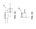
With reference to FIG. 1C, an illustrated exemplary construct template IF-END IF 194 is predefined by the user or system administrator as a pattern of blocks for the graphical modeling or computing environment.
With reference to FIG. 1D, an illustrated exemplary construct template IF-END IF 196 is predefined by the user or system administrator as a flowchart for the graphical modeling or computing environment.
With reference to FIG. 1E, an illustrated exemplary construct template IF-END IF 198 is predefined by the user or system administrator as text for the text-based modeling or computing environment.
With reference to FIG. 1F, an illustrated exemplary construct template TOP LEVEL ARCHITECTURE 199 is predefined by the user or system administrator for the graphical modeling or computing environment.
Other examples of the constructs, which may be predefined by the user, include IF-cascade of ELSE IF-END IF, SWITCH condition—cascade of CASE, DO-WHILE loop, REPEAT-UNTIL loop, IF-nested IF condition-nested IF condition-END IF-END IF, FOR loop, SIMPLE STATE MACHINE, IF-THEN-ELSE-IF, IF-THEN-IF, IF-THEN, IF-THEN-ELSE, IF, cascade of IF-THEN, FOR-WHILE, FOR-loop, WHILE-loop, case, combination of logical signals, vector signals, conditions, conditions with subconditions, conditions which are visually separated, UNLESS conditions, a proportional-integral-derivative (PID) controller, a proportional-integral (PI) controller, a proportional-derivative (PD) controller, an integral-derivative (ID) controller, a proportional (P) controller, a derivative (D) controller, first order through nth order filters as well as other kind of filters, joints, arms, masses, pipes, pressure vessels and combinations thereof, etc. The constructs may include parameterized constructs. For example, for a SWITCH construct, the user may be queried for a number of cases.
The communication interface 132 may include any transceiver like mechanism that enables the computer 110 to communicate with other devices and/or systems, such as client computers. For example, the communication interface 132 may include one or more interfaces. Alternatively, the communication interface 132 may include other mechanisms for communicating via a network, such as a wireless network. In one implementation, the communication interface 132 may include logic to send code to a destination device, such as a target device that can include general purpose hardware (e.g., a personal computer form factor), dedicated hardware (e.g., a digital signal processing (DSP) device or a field programmable gate array (FPGA) adapted to execute a compiled version of a model or a part of a model), etc.
The computer 110 may perform certain functions in response to the processor 114 executing software instructions included in the computer-readable medium, such as memory 116. A computer-readable medium may be defined as one or more memory devices. In alternative embodiments, hardwired circuitry may be used in place of or in combination with software instructions to implement features consistent with principles of the exemplary embodiments. Thus, implementations consistent with principles of the application are not limited to any specific combination of hardware circuitry and software.
With continuing reference to FIG. 1A and further reference to FIG. 2A, the user may select the construct icon 182 on the design tool screen 170 with the input device 122 and place the selected construct icon 182 into the computing environment interface screen 172, 174 associated with the desired computing environment such as the textual computing environment 154 or graphical computing environment 156. For example, the user may click with the input device, such as the mouse 122, on the construct icon 182 associated with a respective construct 176 within, for example, a list of construct icons 182 displayed in the design tool bar window 170, may select an appropriate entry from a pull down menu, and the like. The user may drag the selected construct icon 182 with the mouse 122, release the mouse 122 and drop the dragged construct icon 182 into one of the computing environment interface screens 172, 174 which each interfaces with a respective one of the computing environments 154, 156. A monitor 220 may monitor the design tool bar window 170, detect that the construct icon 182 is selected and dropped into one of the computing environment interface screens 172, 174. More specifically, a construct determining mechanism, device, algorithm, processor, software module, or other means 230 may determine a type of a construct 176 associated with the selected construct icon 182 and placed by the user into the computing environment screen 172, 174.
A computing environment determining mechanism, device, algorithm, processor, software module, or other means 240 may determine a type of the computing environment into which the user dropped the selected construct icon 182. A position determining mechanism, device, algorithm, processor, software module, or other means 250 may determine a position into which the construct icon 182 is dropped. A template selector, mechanism, device, algorithm, processor, software module, or other means 258 may select an appropriate template based on the determined type of the selected computing environment 154, 156 and/or other criteria such as preferred style which may be entered by the user or selected automatically based on user identification.
With reference to FIG. 2B, the user may select a construct icon 260 representing and associated, for example, with a construct “DO-WHILE”. For example, if the user drops the selected construct icon 260 into a text-based modeling or computing environment screen 262, a corresponding template including text “DO-WHILE” 264 is selected. If the user drops the selected construct icon 260 into a block-based graphical modeling or computing environment screen 266, a corresponding template including block diagram 268 representing the construct “DO-WHILE” is selected. If the user drops the selected construct icon 260 into a chart-based graphical modeling or computing environment screen 270, a corresponding template including a flowchart 272 representing the construct “DO-WHILE” is selected.
With reference again to FIG. 2A, a template inserter, mechanism, device, algorithm, processor, software module, or other means 280 may insert the selected template at the determined position in the computing environment 154, 156 with the knowledge of context. After the model is created in the manner described above, time-dependent mathematical relationships among the selected system's inputs, states, and outputs may be determined. The system further may be simulated from a specified start time to a specified stop time. The deployable software systems or descriptions of hardware systems that mimic the behavior of either the entire model or portions of the model may be produced.
With reference again to FIG. 1A and further reference to FIG. 3, the user may select 310 the construct icon 182 on the design tool bar window 170 with the mouse 122. The user may drag 320 the selected construct icon 182 into a selected computing environment interface screen 172, 174. A type of the construct 176 associated with the selected construct icon 182 may be determined 322. The user may drop 330 the dragged construct icon 182 into the selected computing environment interface screen 172, 174 which interfaces with respective textual or graphical computing environment 154, 156. A position of the dropped construct icon 182 may be determined 340. A type of the selected computing environment 154, 156 may be determined 350. A template, corresponding to the selected construct and selected computing environment, may be selected 360. The selected template may be inserted 370 in the position of determined construct icon drop.
With continuing reference to FIG. 1A and further reference to FIG. 4A, first second, third, . . . , Nth client computers 400, 410, 420, 430 of selected users may be interconnected through a network 440. For example, the selected users all are employees of the same entity such as a corporation or the same department within the entity. Each client computer 400, 410, 420, 430 is embodied similarly to the computer 110 of FIG. 1A and includes at least the components of the computer 110 as described above. A construct creating mechanism, device, algorithm, processor, software module, or other means 442 facilitates modifications of the design tool 152 and design tool bar window 170 based, for example, on a user input.
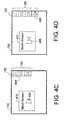
With continuing reference to FIGS. 1A and 4A and further reference to FIGS. 4B and 4C, the user may create or modify the constructs 176, construct icons 182, or the constructs palette 180. The user may build a new construct using the existent constructs. The construct palette 180 may display first icon or icons 452 for the predefined constructs and second icon or icons 454 for user created constructs. For example, the user may add, delete, rename, or export the constructs. The user may click on a pattern icon, button, wizard or window 460 which may guide the user through the pattern building steps. For example, the user may be presented with a pull down menu, windows or icons to select a computing environment in which the user prefers to build a new pattern. The icons may include a block icon 462 for the block-based graphical modeling or computing environment, a flowchart icon 464 for the chart-based graphical modeling or computing environment, or a text icon 466 for the text-based modeling or computing environment. The user may select the block icon 462 to build the new pattern as a block diagram in the block-based graphical modeling or computing environment. A block screen or window 470 may be displayed. The user may create a new pattern 472 on the block screen 470 by using the mouse 122. The user may associate the created pattern 472 with a construct icon 474 by dragging the created pattern with the mouse 122 and placing the created pattern 472 on the construct palette 180 in the area 454 for the user created constructs. The pattern icon 460 may guide the user to populate other computing environments represented by a flowchart screen or window 476 for the chart-based graphical modeling or computing environment and a text screen or window 478 for the text-based modeling or computing environment. The user may drag the created construct 472 with the mouse 122 and drop the created construct 472 into the flowchart screen and the text screen 476, 478. The design tool 152 may restructure the dropped construct for the appropriate computing environment context. It is contemplated that the construct palette 180 may be organized by the users according to their preferences.
In one exemplary embodiment, the user may click on the pattern wizard 460 which may guide the user through the building steps for a pattern template or construct which is independent and different from any computing environment. The design tool may convert the construct created in such independent environment into a block for the block-based graphical modeling or computing environment, a flowchart for the chart-based graphical modeling or computing environment, or a text for the text-based modeling or computing environment depending on into which environment the construct is inserted.
The modified or newly created construct may be saved in the design tool 152. For example, when the modifications are made to the design tool 152 and/or the design tool bar window 170 by the user of the first computer 400, an exporting/importing mechanism 480 propagates the modifications to the design tools 152 and/or design tool bar windows 170 of the second, third, and Nth client computers 410, 420, 430. In one embodiment, the design tool 152 and/or design tool bar window 170 of each client computer 410, 420, 430 is updated by broadcasting a message among the client computers 400, 410, 420, 430. In another embodiment, the design tool 152 and/or design tool bar window 170 of each client computer 400, 410, 420, 430 is automatically updated via an updating mechanism 482 such as a server using, for example, a push or a pull protocol known in the art.
In one embodiment, a host computer may embody the construct creating mechanism 442 to modify the constructs, etc. and/or the exporting/importing mechanism 482 to make newly created constructs available for use by the users of the selected computers.
With continuing reference to FIG. 1A and further reference to FIG. 4C, a construct can be created by using a multi-touch sensing or rear-projecting device embodied within the display 130. The user may touch and hold the construct icon 484 and touch a point 486 in the block screen. Alternatively, this may be a drag and drop operation. A resulting new pattern or construct 488 is illustrated in FIG. 4D. As described above, the newly created construct 488 may be saved in the design tool 152. The construct palette 180 may be updated with an icon 490 corresponding to the newly created construct 488.
With reference to FIG. 5, the exemplary embodiment of FIG. 1A may be embodied as a computer system 500 which may include a computer 510. The computer 510 may include a computer readable medium 520 embodying software for implementing the systems and methods described herein to operate the computer 510. Optionally, the computer system 500 includes a connection 530 to a network 540 for the computer 510 to send and receive information such as software, data, documents and the like from other computer systems.
The design tool may be embodied in many different ways as a software component. For example, it may be a stand-alone software package, or it may be a software package incorporated as a “tool” in a larger software product, such as, for example, a mathematical analysis product or a test generation product. It may be downloadable from a network, for example, a website, as a stand-alone product or as an add-in package for installation in an existing software application. It may also be available as a client-server software application, or as a web-enabled software application.
The methods and tools described above allow the user to drag and drop entire design constructs into the modeling computing environment. The cross environment design tool provides the template functionality based on predefined and customizable design patterns seamlessly working across textual and graphical computing environments.
Further, the described design tool provides users at-design-time support and guidance to keep their models clean and efficient.
Generally, any architectural structure can be utilized, such as multi-core, multi-device (e.g., distributed configurations), LAN events and the like.
Certain portions of the exemplary embodiments may be implemented as “logic” that performs one or more functions. This logic may include hardware, such as hardwired logic, an application specific integrated circuit, a field programmable gate array, a microprocessor, software, or a combination of hardware and software.
No element, act, or instruction used in the description of the exemplary embodiments should be construed as critical or essential to the exemplary embodiments unless explicitly described as such. Also, as used herein, the article “a” is intended to include one or more items. Where only one item is intended, the term “one” or similar language is used. Further, the phrase “based on,” as used herein is intended to mean “based, at least in part, on” unless explicitly stated otherwise.
While various embodiments have been described above, it should be understood that they have been presented by way of example only, and not limitation. Thus, the breadth and scope of the described should not be limited by any of the above-described exemplary embodiments, but should instead be defined only in accordance with the following claims and their equivalents.

Claims (22)

What is claimed is:
1. A computer-implemented method for inserting content into a model using a design tool, the method comprising:
displaying, by a computer, a list of user-selectable construct icons on a user interface screen of the design tool, the construct icons associated with constructs;
determining, by the computer, a construct icon selected by the user;
displaying, by the computer, a plurality of computing environment interface screens able to receive the selected construct icon, the plurality of computing environment interface screens being simultaneously displayed on the user interface screen of the design tool and associated with a plurality of computing environments including at least one textual computing environment and at least one graphical computing environment;
receiving, by the computer, a selection of a selected computing environment interface screen from the plurality of computing environment interface screens into which the construct associated with the user selected construct icon is placed;
identifying, by the computer, a selected computing environment from the plurality of computing environments, wherein the selected computing environment is associated with the selected computing environment interface screen;
determining, by the computer, a position of the placed construct in the selected computing environment;
selecting, by the computer, a template based on the selected computing environment and the placed construct; and
inserting, by the computer, the selected template into the selected computing environment at the determined position in the selected computing environment.
2. The method according to claim 1, wherein the textual computing environment includes at least one of a C environment, a Python environment, a Javascript environment, an Octave environment, a dynamically typed language environment, or Hardware Description Language environment, and the graphical computing environment includes at least one of a time-based graphical modeling environment, a block-based environment, a chart-based environment, a state-based diagram environment, a data flow diagram environment, an entity flow network diagram environment, an electronic design automation environment, a Schematic Layout environment, or a Unified Modeling Language environment.
3. The method according to claim 1, wherein the construct includes computer-readable medium encoded with at least one of:
IF-END-IF,
IF-cascade of ELSE IF-END IF,
SWITCH condition—cascade of CASE,
DO-WHILE loop,
REPEAT-UNTIL loop,
Proportional-Integral-Derivative controller,
Proportional-Integral controller,
Proportional-Derivative controller,
Integral-Derivative controller,
Proportional controller,
Derivative controller,
Integral controller,
IF-nested IF condition-nested IF condition-END IF-END IF,
FOR loop,
SIMPLE STATE MACHINE,
TOP LEVEL ARCHITECTURE,
IF-THEN-ELSE-IF,
IF-THEN-IF,
IF-THEN,
IF-THEN-ELSE,
IF,
cascade of IF-THEN,
FOR-WHILE,
FOR-loop,
WHILE-loop,
parameterized construct,
case,
combination of logical signals,
vector signals,
conditions,
conditions with subconditions,
UNLESS conditions,
algorithmic components,
physical systems,
physical subsystems, or
conditions which are visually separated.
4. The method according to claim 1, further comprising:
creating a construct based on a user input;
storing the construct in the design tool;
creating a second construct icon that corresponds to the created construct; and
displaying the second construct icon corresponding to the created construct in the list of constructs on the user interface screen.
5. The method according to claim 4, further comprising:
at least one of exporting or importing the created construct among selected client computers; and
sharing the created construct by users of the selected computers.
6. The method according to claim 5, further comprising:
automatically updating design tools of the selected client computers with the created construct.
7. The method according to claim 6, further comprising:
automatically updating a list of constructs of a user interface screen associated with each selected computer with the second construct icon; and
displaying the second construct icon in the updated list of constructs of the user interface screen of each selected computer.
8. A method for designing models, comprising at least one of:
downloading software to a computer system, which software, when executed by the computer system, causes the computer system to perform operations comprising the method of claim 1; or
providing downloadable software to a computer system, which software, when executed by the computer system, causes the computer system to perform operations comprising the method of claim 1.
9. At least one non-transitory computer-readable medium comprising software that, when executed by a computer, causes the computer to perform operations for designing models with a design tool, the at least one computer-readable medium comprising:
one or more instructions for displaying a list of user-selectable construct icons on a user interface screen of the design tool, the construct icons associated with constructs;
one or more instructions for determining a construct icon selected by the user;
one or more instructions for presenting a plurality of computing environment interface screens able to receive the selected construct icon, the plurality of computing environment interface screens being simultaneously displayed on the user interface screen of the design tool and associated with a plurality of computing environments including at least one textual computing environment and at least one graphical computing environment;
one or more instructions for receiving a selection of a selected computing environment interface screen from the plurality of computing environment interface screens into which the construct associated with the user selected construct icon is placed;
one or more instructions for identifying a selected computing environment from the plurality of computing environments based on the selected computing environment interface screen;
one or more instructions for determining a position at which the selected construct is placed into the selected computing environment;
one or more instructions for selecting a template based on the selected computing environment and the placed construct; and
one or more instructions for inserting the selected template into the selected computing environment at the determined position in the selected computing environment.
10. The at least one non-transitory computer-readable medium according to claim 9, wherein the textual computing environment includes at least one of a C environment, a Python environment, a Javascript environment, an Octave environment, a dynamically typed language environment, or Hardware Description Language environment and the graphical computing environment includes at least one of a time-based graphical modeling environment, a block-based environment, a chart-based environment, a state-based diagram environment, a data flow diagram environment, an entity flow network diagram environment, an electronic design automation environment, a Schematic Layout environment, or a Unified Modeling Language environment.
11. The at least one non-transitory computer-readable medium according to claim 9, wherein the construct includes at least one of:
IF-END-IF,
IF-cascade of ELSE IF-END IF,
SWITCH condition—cascade of CASE,
DO-WHILE loop,
REPEAT-UNTIL loop,
Proportional-Integral-Derivative controller,
Proportional-Integral controller,
Proportional-Derivative controller,
Integral-Derivative controller,
Proportional controller,
Derivative controller,
Integral controller,
IF-nested IF condition-nested IF condition-END IF-END IF,
FOR loop,
SIMPLE STATE MACHINE,
TOP LEVEL ARCHITECTURE,
IF-THEN-ELSE-IF,
IF-THEN-IF,
IF-THEN,
IF-THEN-ELSE,
IF,
cascade of IF-THEN,
FOR-WHILE,
FOR-loop,
WHILE-loop,
parameterized construct,
case,
combination of logical signals,
vector signals,
conditions,
conditions with subconditions,
UNLESS conditions,
algorithmic components,
physical systems,
physical subsystems, or
conditions which are visually separated.
12. The at least one non-transitory computer-readable medium according to claim 9, further comprising:
one or more instructions for creating a construct based on a user input;
one or more instructions for storing the construct in the design tool;
one or more instructions for creating a second construct icon which corresponds to the created construct; and
one or more instructions for displaying the second construct icon corresponding to the created construct in the list of constructs on the user interface screen.
13. The at least one non-transitory computer-readable medium according to claim 12, further comprising:
one or more instructions for at least one of exporting or importing the created construct among selected client computers.
14. The at least one non-transitory computer-readable medium according to claim 13, wherein one or more instructions for at least one of exporting and importing the created construct comprises:
one or more instructions for automatically updating design tools of the selected client computers with the created construct.
15. The at least one non-transitory computer-readable medium according to claim 14, further comprising:
one or more instructions for automatically updating a list of constructs of a user interface screen associated with each selected computer with the created second construct icon; and
one or more instructions for displaying the created second construct icon in the updated list of constructs of the user interface screen of each selected computer.
16. A system for designing models, comprising:
a display device which displays a list of user-selectable construct icons on a user interface screen, the construct icons associated with constructs and a plurality of computing environment interface screens able to receive the selected construct icon, the plurality of computing environment interface screens being simultaneously displayed on the user interface screen and associated with a plurality of computing environments including at least one textual computing environment and at least one graphical computing environment;
one or more computing systems programmed to perform the following:
determining a construct selected by the user;
receiving a selection of a selected computing environment interface screen from the plurality of computing environment interface screens into which the construct associated with the user selected construct icon is placed;
identifying a selected computing environment from the plurality of computing environments, wherein the selected computing environment is associated with the selected computing environment interface screen;
determining a position at which the construct is placed into the selected computing environment;
selecting a template based on the selected computing environment and the placed construct; and
inserting the selected template into the selected computing environment at the determined position and interconnecting the inserted construct with content of the selected computing environment at the position of insertion.
17. The system according to claim 16, wherein the textual computing environment includes at least one of a C environment, a Python environment, a Javascript environment, an Octave environment, a dynamically typed language environment, or Hardware Description Language environment and the graphical computing environment includes at least one of a time-based graphical modeling environment, a block-based environment, a chart-based environment, a state-based diagram environment, a data flow diagram environment, an entity flow network diagram environment, an electronic design automation environment, a Schematic Layout environment, or a Unified Modeling Language environment.
18. The system according to claim 16, wherein the construct includes at least one of:
IF-END-IF,
IF-cascade of ELSE IF-END IF,
SWITCH condition—cascade of CASE,
DO-WHILE loop,
REPEAT-UNTIL loop,
Proportional-Integral-Derivative controller,
Proportional-Integral controller,
Proportional-Derivative controller,
Integral-Derivative controller,
Proportional controller,
Derivative controller,
Integral controller,
IF-nested IF condition-nested IF condition-END IF-END IF,
FOR loop,
SIMPLE STATE MACHINE,
TOP LEVEL ARCHITECTURE,
IF-THEN-ELSE-IF,
IF-THEN-IF,
IF-THEN,
IF-THEN-ELSE,
IF,
cascade of IF-THEN,
FOR-WHILE,
FOR-loop,
WHILE-loop,
parameterized construct,
case,
combination of logical signals,
vector signals,
conditions,
conditions with subconditions,
UNLESS conditions,
algorithmic components,
physical systems,
physical subsystems, or
conditions which are visually separated.
19. The system according to claim 16, wherein the one or more computing systems are further programmed to perform the following:
creating a construct based on a user input;
storing the construct;
creating a second construct icon which corresponds to the created construct; and
displaying the second construct icon corresponding to the created construct in the list of constructs on the user interface screen.
20. The system according to claim 19, wherein the one or more computing systems are further programmed to perform at least one of exporting or importing the created construct among selected client computers.
21. The system according to claim 20, wherein the exporting and importing automatically updates selected client computers with the created construct and displays the created construct icon on selected client computers.
22. A system for designing models, comprising:
a graphical user interface which displays a list of user-selectable construct icons, the construct icons associated with constructs; and
a processor which is programmed to perform steps of:
presenting the list of construct icons on the graphical user interface,
determining the construct icon selected by the user,
displaying a plurality of computing environment interface screens on the graphical user interface, the computing environment interface screens are able to receive the selected construct icon, the plurality of computing environment interface screens being simultaneously displayed and associated with a plurality of computing environments including at least one textual computing environment and at least one graphical computing environment,
receiving, a selection of a selected computing environment interface screen from the plurality of computing environment interface screens into which the construct associated with the user selected construct icon is placed,
identifying a computing environment from the plurality of computing environments, wherein the selected computing environment is associated with the selected computing environment interface screen the construct,
determining a position of the placed construct in the selected computing environment,
selecting a template based on the selected computing environment and the placed construct,
inserting the selected template into the selected computing environment at the determined position in the selected computing environment,
interconnecting the selected template with content of the selected computing environment at the position of insertion, and
displaying the designed model on the graphical user interface.
US11/882,825 2025-08-07 2025-08-07 Pattern modeling methods and systems Active 2025-08-07 US8776015B1 (en)

Priority Applications (1)

Application Number Priority Date Filing Date Title
US11/882,825 US8776015B1 (en) 2025-08-07 2025-08-07 Pattern modeling methods and systems

Applications Claiming Priority (2)

Application Number Priority Date Filing Date Title
US11/703,732 US8336025B1 (en) 2025-08-07 2025-08-07 Pattern modeling methods and systems
US11/882,825 US8776015B1 (en) 2025-08-07 2025-08-07 Pattern modeling methods and systems

Related Parent Applications (1)

Application Number Title Priority Date Filing Date
US11/703,732 Continuation-In-Part US8336025B1 (en) 2025-08-07 2025-08-07 Pattern modeling methods and systems

Publications (1)

Publication Number Publication Date
US8776015B1 true US8776015B1 (en) 2025-08-07

Family

ID=51031977

Family Applications (1)

Application Number Title Priority Date Filing Date
US11/882,825 Active 2025-08-07 US8776015B1 (en) 2025-08-07 2025-08-07 Pattern modeling methods and systems

Country Status (1)

Country Link
US (1) US8776015B1 (en)

Cited By (4)

* Cited by examiner, ? Cited by third party
Publication number Priority date Publication date Assignee Title
US10620802B1 (en) * 2025-08-07 2025-08-07 Cadence Design Systems, Inc. Algorithmic modeling interface process
US11283868B2 (en) * 2025-08-07 2025-08-07 Agarik Sas System and method for scheduling computer tasks
US20220276842A1 (en) * 2025-08-07 2025-08-07 Schneider Electric USA, Inc. Customized software application template-based generator
US20220326913A1 (en) * 2025-08-07 2025-08-07 Accenture Global Solutions Limited Simulation-based software design and delivery attribute tradeoff identification and resolution

Citations (55)

* Cited by examiner, ? Cited by third party
Publication number Priority date Publication date Assignee Title
US5187788A (en) * 2025-08-07 2025-08-07 The United States Of America As Represented By The Secretary Of The Air Force Graphics system for automatic computer code generation
US6151699A (en) * 2025-08-07 2025-08-07 Fujitsu Limited Computer apparatus and method for editing programs, and readable medium
US6289513B1 (en) * 2025-08-07 2025-08-07 Isaac Bentwich Interactive application generation and text processing
US20010034879A1 (en) * 2025-08-07 2025-08-07 Washington Jeffrey D. System and method for programmatically generating a graphical program in response to user input
US20020091990A1 (en) * 2025-08-07 2025-08-07 Todd Little System for software application development and modeling
US20020196282A1 (en) * 2025-08-07 2025-08-07 Washington Jeffrey D. Collector node for a graphical program
US6553268B1 (en) * 2025-08-07 2025-08-07 Rockwell Automation Technologies, Inc. Template language for industrial controller programming
US6606740B1 (en) * 2025-08-07 2025-08-07 American Management Systems, Inc. Development framework for case and workflow systems
US20030167455A1 (en) * 2025-08-07 2025-08-07 Jose Iborra Automatic software production system
US20040111702A1 (en) * 2025-08-07 2025-08-07 Chan Kin Ming Method and apparatus for visual programming
US20040205691A1 (en) * 2025-08-07 2025-08-07 International Business Machines Corporation Interactive agent for a topological multi-tier business application composer
US6836878B1 (en) * 2025-08-07 2025-08-07 International Business Machines Corporation Visual programming from a tree structure
US20050107998A1 (en) 2025-08-07 2025-08-07 The Mathworks, Inc. Propagation of characteristics in a graphical model environment
US20050216248A1 (en) 2025-08-07 2025-08-07 The Mathworks, Inc. System and method for block diagram simulation context restoration
US20050216887A1 (en) * 2025-08-07 2025-08-07 William Robertson Document development platform
US20050229154A1 (en) * 2025-08-07 2025-08-07 Complementsoft Llc System and method for generating and maintaining software code
US20050278162A1 (en) 2025-08-07 2025-08-07 The Mathworks, Inc. Variants in graphical modeling environments
US6986120B2 (en) * 2025-08-07 2025-08-07 Tata Consultancy Services Limited System and apparatus for programming system views in an object oriented environment
US20060015839A1 (en) * 2025-08-07 2025-08-07 Peter Owens Development of software systems
US20060064670A1 (en) * 2025-08-07 2025-08-07 The Mathworks, Inc. Generation of code from a graphical model
US20060129371A1 (en) 2025-08-07 2025-08-07 The Mathworks, Inc. Tools for system-level design environments
US20060139372A1 (en) 2025-08-07 2025-08-07 The Mathworks, Inc. Providing graphic generating capabilities for a model based development process
US20060168558A1 (en) * 2025-08-07 2025-08-07 De Seabra E Melo Miguel A C Software development system and method
US7088377B2 (en) * 2025-08-07 2025-08-07 Cook Jonathan B System and method for designing, synthesizing and analyzing computer generated mechanisms
US7114146B2 (en) * 2025-08-07 2025-08-07 International Business Machines Corporation System and method of dynamic service composition for business process outsourcing
US20060235548A1 (en) 2025-08-07 2025-08-07 The Mathworks, Inc. Graphical state machine based programming for a graphical user interface
US20060242223A1 (en) 2025-08-07 2025-08-07 The Mathworks, Inc. System and method for using an RMI activation system daemon with non-Java applications
US20070061778A1 (en) * 2025-08-07 2025-08-07 Sadlek James M Visual programming method
US20070150864A1 (en) * 2025-08-07 2025-08-07 Goh Chee Ying Josiah Visual-Based Object Oriented Programming Language & System
US20070192759A1 (en) * 2025-08-07 2025-08-07 Mitsubishi Electric Corporation Diagram editing apparatus
US7272708B1 (en) * 2025-08-07 2025-08-07 Veritas Operating Corporation System for configuration of dynamic computing environments using a visual interface
US7275096B2 (en) * 2025-08-07 2025-08-07 Telelogic North America Inc. Computerized system and method for web enabling and/or web management of embedded applications
US7334216B2 (en) * 2025-08-07 2025-08-07 Sosy, Inc. Method and apparatus for automatic generation of information system user interfaces
US20080120594A1 (en) * 2025-08-07 2025-08-07 Bruce David Lucas System and method for managing resources using a compositional programming model
US20080148221A1 (en) * 2025-08-07 2025-08-07 Letkeman Kim D Dynamic multi-context delta view for merging structured data in a visual merge tool
US20080301625A1 (en) * 2025-08-07 2025-08-07 Bea Systems, Inc. System and method for creating and updating a data model from disparate events received on arbitrary application threads
US7484201B2 (en) * 2025-08-07 2025-08-07 Sony Corporation Nonlinear editing while freely selecting information specific to a clip or a track
US7496888B2 (en) * 2025-08-07 2025-08-07 International Business Machines Corporation Solution builder wizard
US20090070738A1 (en) * 2025-08-07 2025-08-07 The Mathworks, Inc. Integrating program construction
US7506306B2 (en) * 2025-08-07 2025-08-07 International Business Machines Corporation Graphical editor with incremental development
US20090089746A1 (en) * 2025-08-07 2025-08-07 International Business Machines Corporation Method and System for Generating Application Data Editors
US7536676B2 (en) * 2025-08-07 2025-08-07 Newalliance Bank Object process graph application controller-viewer
US7543267B2 (en) * 2025-08-07 2025-08-07 Microsoft Corporation Drag and drop creation and editing of a page incorporating scripts
US20090144439A1 (en) * 2025-08-07 2025-08-07 Rudy Ziegler Method and system for streaming images to wireless devices
US7553942B2 (en) 2025-08-07 2025-08-07 Ge Healthcare Limited Method for the use of [11C] carbon monoxide in labeling synthesis of 11C-labelled amides using metal amides and photo-induced free radical carbonylation
US20090241089A1 (en) * 2025-08-07 2025-08-07 Subramanian Ramamoorthy Converting a First Graphical Program into a Second Graphical Program Using an Intermediate Abstract Representation
US20100070945A1 (en) * 2025-08-07 2025-08-07 Tattrie Scott I Custom and customizable components, such as for workflow applications
US20100088664A1 (en) * 2025-08-07 2025-08-07 Payman Khodabandehloo Design tool and methodology for enterprise software applications
US20100211638A1 (en) * 2025-08-07 2025-08-07 Goojet Method and device for creating computer applications
US7802230B1 (en) * 2025-08-07 2025-08-07 Sap Ag Heterogeneous software integration systems and methods
US20110010686A1 (en) * 2025-08-07 2025-08-07 Computer Associates Think, Inc. System and method for integrating object-oriented model profiles and object-oriented programming languages
US8266579B2 (en) * 2025-08-07 2025-08-07 International Business Machines Corporation System and method for developing and deploying a model-driven editor
US20130179775A1 (en) * 2025-08-07 2025-08-07 International Business Machines Corporation Data editing for improving readability of a display
US8522196B1 (en) * 2025-08-07 2025-08-07 The Mathworks, Inc. Traceability in a modeling environment
US8533666B2 (en) * 2025-08-07 2025-08-07 Microsoft Corporation Interactive design environments to visually model, debug and execute resource oriented programs

Patent Citations (61)

* Cited by examiner, ? Cited by third party
Publication number Priority date Publication date Assignee Title
US5187788A (en) * 2025-08-07 2025-08-07 The United States Of America As Represented By The Secretary Of The Air Force Graphics system for automatic computer code generation
US6836878B1 (en) * 2025-08-07 2025-08-07 International Business Machines Corporation Visual programming from a tree structure
US6553268B1 (en) * 2025-08-07 2025-08-07 Rockwell Automation Technologies, Inc. Template language for industrial controller programming
US6151699A (en) * 2025-08-07 2025-08-07 Fujitsu Limited Computer apparatus and method for editing programs, and readable medium
US6606740B1 (en) * 2025-08-07 2025-08-07 American Management Systems, Inc. Development framework for case and workflow systems
US7543267B2 (en) * 2025-08-07 2025-08-07 Microsoft Corporation Drag and drop creation and editing of a page incorporating scripts
US6289513B1 (en) * 2025-08-07 2025-08-07 Isaac Bentwich Interactive application generation and text processing
US20010034879A1 (en) * 2025-08-07 2025-08-07 Washington Jeffrey D. System and method for programmatically generating a graphical program in response to user input
US20090241089A1 (en) * 2025-08-07 2025-08-07 Subramanian Ramamoorthy Converting a First Graphical Program into a Second Graphical Program Using an Intermediate Abstract Representation
US20030167455A1 (en) * 2025-08-07 2025-08-07 Jose Iborra Automatic software production system
US6681383B1 (en) * 2025-08-07 2025-08-07 Sosy, Inc. Automatic software production system
US7334216B2 (en) * 2025-08-07 2025-08-07 Sosy, Inc. Method and apparatus for automatic generation of information system user interfaces
US7088377B2 (en) * 2025-08-07 2025-08-07 Cook Jonathan B System and method for designing, synthesizing and analyzing computer generated mechanisms
US7272708B1 (en) * 2025-08-07 2025-08-07 Veritas Operating Corporation System for configuration of dynamic computing environments using a visual interface
US7047518B2 (en) 2025-08-07 2025-08-07 Bea Systems, Inc. System for software application development and modeling
US20020091990A1 (en) * 2025-08-07 2025-08-07 Todd Little System for software application development and modeling
US20050229154A1 (en) * 2025-08-07 2025-08-07 Complementsoft Llc System and method for generating and maintaining software code
US20020196282A1 (en) * 2025-08-07 2025-08-07 Washington Jeffrey D. Collector node for a graphical program
US20090228864A1 (en) * 2025-08-07 2025-08-07 Washington Jeffrey D Collector Node for a Graphical Program
US7484201B2 (en) * 2025-08-07 2025-08-07 Sony Corporation Nonlinear editing while freely selecting information specific to a clip or a track
US6986120B2 (en) * 2025-08-07 2025-08-07 Tata Consultancy Services Limited System and apparatus for programming system views in an object oriented environment
US20040205691A1 (en) * 2025-08-07 2025-08-07 International Business Machines Corporation Interactive agent for a topological multi-tier business application composer
US7275096B2 (en) * 2025-08-07 2025-08-07 Telelogic North America Inc. Computerized system and method for web enabling and/or web management of embedded applications
US8522196B1 (en) * 2025-08-07 2025-08-07 The Mathworks, Inc. Traceability in a modeling environment
US20040111702A1 (en) * 2025-08-07 2025-08-07 Chan Kin Ming Method and apparatus for visual programming
US20060015839A1 (en) * 2025-08-07 2025-08-07 Peter Owens Development of software systems
US20110010686A1 (en) * 2025-08-07 2025-08-07 Computer Associates Think, Inc. System and method for integrating object-oriented model profiles and object-oriented programming languages
US7114146B2 (en) * 2025-08-07 2025-08-07 International Business Machines Corporation System and method of dynamic service composition for business process outsourcing
US20130179775A1 (en) * 2025-08-07 2025-08-07 International Business Machines Corporation Data editing for improving readability of a display
US20050216248A1 (en) 2025-08-07 2025-08-07 The Mathworks, Inc. System and method for block diagram simulation context restoration
US20100070945A1 (en) * 2025-08-07 2025-08-07 Tattrie Scott I Custom and customizable components, such as for workflow applications
US20050107998A1 (en) 2025-08-07 2025-08-07 The Mathworks, Inc. Propagation of characteristics in a graphical model environment
US20050216887A1 (en) * 2025-08-07 2025-08-07 William Robertson Document development platform
US20050278162A1 (en) 2025-08-07 2025-08-07 The Mathworks, Inc. Variants in graphical modeling environments
US7536676B2 (en) * 2025-08-07 2025-08-07 Newalliance Bank Object process graph application controller-viewer
US20060064670A1 (en) * 2025-08-07 2025-08-07 The Mathworks, Inc. Generation of code from a graphical model
US20120131545A1 (en) * 2025-08-07 2025-08-07 The Mathworks, Inc. Generation of code from a graphical model
US20090144439A1 (en) * 2025-08-07 2025-08-07 Rudy Ziegler Method and system for streaming images to wireless devices
US7553942B2 (en) 2025-08-07 2025-08-07 Ge Healthcare Limited Method for the use of [11C] carbon monoxide in labeling synthesis of 11C-labelled amides using metal amides and photo-induced free radical carbonylation
US20060129371A1 (en) 2025-08-07 2025-08-07 The Mathworks, Inc. Tools for system-level design environments
US20060139372A1 (en) 2025-08-07 2025-08-07 The Mathworks, Inc. Providing graphic generating capabilities for a model based development process
US20060168558A1 (en) * 2025-08-07 2025-08-07 De Seabra E Melo Miguel A C Software development system and method
US7496888B2 (en) * 2025-08-07 2025-08-07 International Business Machines Corporation Solution builder wizard
US20060242223A1 (en) 2025-08-07 2025-08-07 The Mathworks, Inc. System and method for using an RMI activation system daemon with non-Java applications
US20060235548A1 (en) 2025-08-07 2025-08-07 The Mathworks, Inc. Graphical state machine based programming for a graphical user interface
US7506306B2 (en) * 2025-08-07 2025-08-07 International Business Machines Corporation Graphical editor with incremental development
US20120054717A1 (en) * 2025-08-07 2025-08-07 International Business Machines Corporation Graphical Editor with Incremental Development
US20070061778A1 (en) * 2025-08-07 2025-08-07 Sadlek James M Visual programming method
US7949995B2 (en) * 2025-08-07 2025-08-07 Sadlek James M Visual programming method
US7802230B1 (en) * 2025-08-07 2025-08-07 Sap Ag Heterogeneous software integration systems and methods
US8266579B2 (en) * 2025-08-07 2025-08-07 International Business Machines Corporation System and method for developing and deploying a model-driven editor
US20070150864A1 (en) * 2025-08-07 2025-08-07 Goh Chee Ying Josiah Visual-Based Object Oriented Programming Language & System
US20070192759A1 (en) * 2025-08-07 2025-08-07 Mitsubishi Electric Corporation Diagram editing apparatus
US20090089746A1 (en) * 2025-08-07 2025-08-07 International Business Machines Corporation Method and System for Generating Application Data Editors
US20100088664A1 (en) * 2025-08-07 2025-08-07 Payman Khodabandehloo Design tool and methodology for enterprise software applications
US20080120594A1 (en) * 2025-08-07 2025-08-07 Bruce David Lucas System and method for managing resources using a compositional programming model
US20080148221A1 (en) * 2025-08-07 2025-08-07 Letkeman Kim D Dynamic multi-context delta view for merging structured data in a visual merge tool
US20090070738A1 (en) * 2025-08-07 2025-08-07 The Mathworks, Inc. Integrating program construction
US20080301625A1 (en) * 2025-08-07 2025-08-07 Bea Systems, Inc. System and method for creating and updating a data model from disparate events received on arbitrary application threads
US20100211638A1 (en) * 2025-08-07 2025-08-07 Goojet Method and device for creating computer applications
US8533666B2 (en) * 2025-08-07 2025-08-07 Microsoft Corporation Interactive design environments to visually model, debug and execute resource oriented programs

Cited By (7)

* Cited by examiner, ? Cited by third party
Publication number Priority date Publication date Assignee Title
US11283868B2 (en) * 2025-08-07 2025-08-07 Agarik Sas System and method for scheduling computer tasks
US11290534B2 (en) 2025-08-07 2025-08-07 Agarik Sas System and method for scheduling computer tasks
US10620802B1 (en) * 2025-08-07 2025-08-07 Cadence Design Systems, Inc. Algorithmic modeling interface process
US20220276842A1 (en) * 2025-08-07 2025-08-07 Schneider Electric USA, Inc. Customized software application template-based generator
US11914975B2 (en) * 2025-08-07 2025-08-07 Schneider Electric USA, Inc. Customized software application template-based generator
US20220326913A1 (en) * 2025-08-07 2025-08-07 Accenture Global Solutions Limited Simulation-based software design and delivery attribute tradeoff identification and resolution
US11886837B2 (en) * 2025-08-07 2025-08-07 Accenture Global Solutions Limited Simulation-based software design and delivery attribute tradeoff identification and resolution

Similar Documents

Publication Publication Date Title
US8336025B1 (en) Pattern modeling methods and systems
US11520956B2 (en) Systems and methods for automatically realizing models for co-simulation
US7930160B1 (en) Electronic markup of executable models
US10360310B2 (en) Self-testing graphical component algorithm specification
US9395889B1 (en) Identification of semantically relevant concepts in a graphical model
US9652213B2 (en) Global optimization and verification of cyber-physical systems using floating point math functionality on a system with heterogeneous hardware components
US6366874B1 (en) System and method for browsing graphically an electronic design based on a hardware description language specification
US8914262B2 (en) Visualization of data dependency in graphical models
US8701084B1 (en) Preview of auto-fix changes to software code
US10719645B1 (en) Model structure analysis with integration of transformed slice
US11314225B2 (en) Systems and methods for evaluating assessments
US8823738B1 (en) Merging electronic diagrams
WO2004023325A1 (en) Polymorphic computational system and method
US20140122026A1 (en) Self-testing Graphical Component Algorithm Specification
US8935137B1 (en) Graphic theoretic linearization of sensitivity analysis
US9176640B1 (en) Method of graphically linking multiple disjoint models
CN103065000B (en) A kind of method of carrying out SysML state machine diagram analysis verification based on model-driven engineering
US9098288B1 (en) Interactive design environment having design tool portion and density display portion
US20150088861A1 (en) Comparison And Merging Of IC Design Data
US8667381B1 (en) Block diagram change history
US8776015B1 (en) Pattern modeling methods and systems
US10970183B1 (en) System and method for improving model performance
US12086204B1 (en) Systems and methods for interactive display of symbolic equations extracted from graphical models
US8700378B1 (en) Symbolic expression propagation to support generating reconfiguration code
US10585997B1 (en) Automatic grouping of signals of a model

Legal Events

Date Code Title Description
AS Assignment 百度 左手小指疼痛预兆什么

Owner name: MATHWORKS, INC., THE, MASSACHUSETTS

Free format text: ASSIGNMENT OF ASSIGNORS INTEREST;ASSIGNORS:HOSAGRAHARA, ARVIND S.;SMITH, PAUL F.;SIGNING DATES FROM 20070730 TO 20070731;REEL/FRAME:019709/0197

STCF Information on status: patent grant

Free format text: PATENTED CASE

CC Certificate of correction
MAFP Maintenance fee payment

Free format text: PAYMENT OF MAINTENANCE FEE, 4TH YEAR, LARGE ENTITY (ORIGINAL EVENT CODE: M1551)

Year of fee payment: 4

MAFP Maintenance fee payment

Free format text: PAYMENT OF MAINTENANCE FEE, 8TH YEAR, LARGE ENTITY (ORIGINAL EVENT CODE: M1552); ENTITY STATUS OF PATENT OWNER: LARGE ENTITY

Year of fee payment: 8

冬天开什么花 不打狂犬疫苗会有什么后果 透析病人吃什么水果好 卵巢多囊是什么意思 元曲是什么意思
早泄是什么原因导致 上皮内瘤变是什么意思 饺子都有什么馅 细菌性肺炎吃什么药 六畜兴旺是什么意思
胎神什么意思 臭屁多是什么原因 一本万利是什么意思 坐蜡什么意思 绝症是什么意思
月经推迟是什么原因 梦见数字是什么意思 脚气是什么样的 肝看什么科 pwp是什么意思
饕餮长什么样hcv9jop2ns3r.cn 什么肉不含嘌呤hcv9jop2ns6r.cn 运钞车押运员是什么人hcv8jop9ns1r.cn 胆红素高吃什么食物能降得快hcv9jop6ns3r.cn 李思思为什么离开央视hcv9jop4ns7r.cn
考护士证需要什么条件beikeqingting.com 八十岁是什么寿hcv7jop6ns1r.cn 萧何字什么hcv7jop5ns0r.cn 画是什么结构aiwuzhiyu.com 胃疼吃什么药好的快hcv8jop4ns8r.cn
总胆固醇高有什么危害hcv7jop5ns4r.cn 雪貂吃什么shenchushe.com 心率过快挂什么科jinxinzhichuang.com 儿童过敏性鼻炎吃什么药hcv8jop3ns7r.cn 子宫在肚脐眼什么位置0735v.com
一什么便什么造句hcv8jop7ns3r.cn babies是什么意思inbungee.com 包面是什么hcv8jop1ns0r.cn 体态是什么意思hcv7jop6ns9r.cn 性功能减退吃什么药hcv7jop6ns9r.cn
百度